
Page 408 - Industrial Power Engineering and Applications Handbook
P. 408
13/382 Industrial Power Engineering and Applications Handbook
Sw-1 F1
I
II
II
II
II
II
II
- 11
%
Q
a 1' B/C - 2 I/C-3 B/C - 2
e
L
C I' I1
8 II
2 II
II I I
II
II
II
II I I I I I I
II I I I I I I
II I I I I I I
II
II
F2
I/C- 1 BE-1 I/C-2 B/C - 2 I/C-3
(52i) (52iv) (52ii) (534 (52iii)
Legends details
Sw - 1 - Control supply ON/OFF switch
F, - F, - Control fuses
ST,, ST?, ST,, ST4 and ST5 - Shunt trip coils of breakers
l/C-l,2,3 or 52(i,ii,iii) - Incoming sources of supplies
B/C-l,2 or 52(iv,v) - Bus couplers.
*Note Normally 2NOs of the interrupters are wired in series to share the arc energy and enhance the contact life.
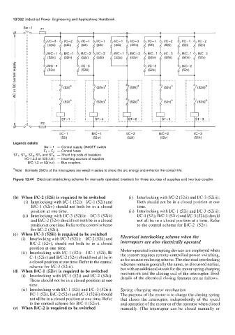
Figure 13.44 Electrical interlocking scheme for manually operated breakers for three sources of supplies and two bus coupler.
(b) When YC-2 (52ii) is required to be switched (i) Interlocking with VC-2 (52ii) and YC-3 (52iii):
(i) Interlocking with I/C-1 (52i): I/C-1 (52i) and Both should not be in a closed position at one
B/C-1 (52iv) should not both be in a closed time.
position at one time. (ii) Interlocking with YC-1 (52i) and YC-3 (52iii):
(ii) Interlocking with YC-3 (52iii): VC-3 (52iii) YC-1 (52i), B/C-I(52iv) and VC-3 (52iii) should
and B/C-2 (52v) should not both be in a closed not all be in a closed position at a time. Refer
position at one time. Refer to the control scheme to the control scheme for B/C-2 (52v).
for I/C-2 (52ii).
(c) When YC-3 (52iii) is required to be switched Electrical interlocking scheme when the
(i) Interlocking with YC-2 (52ii): VC-2 (52ii) and
B/C-2 (52v), should not both be in a closed interrupters are also electrically operated
position at one time.
(ii) Interlocking with I/C-1 (52i): YC-1 (52i), B/ Motor-operated interrupting devices are employed when
the system requires remote-controlled power switching,
C-1 (52iv) and B/C-2 (52v) should not all be in as for an auto-reclosing scheme. The electrical interlocking
a closed position at one time. Refer to the control schemes remain generally the same, as discussed earlier,
scheme for YC-3 (52iii). but with an additional circuit for the motor spring charging
(d) When B/C-1 (52iv) is required to be switched mechanism and the closing coil of the interrupter. Brief
(i) Interlocking with VC-1 (52i) and I/C-2 (52ii): details of the electrical closing features are as follows.
These should not be in a closed position at one
time.
(ii) Interlocking with I/C-1 (52i) and YC-3 (52iii): Spring charging motor mechanism
YC-1 (52i), B/C-2 (52v) and VC-3 (52iii) should The purpose of the motor is to charge the closing spring
not all be in a closed position at one time. Refer that closes the interrupter, independently of the speed
to the control scheme for B/C-1 (52iv). and operation of the motor or of the operator when closed
(e) When B/C-2 is required to be switched manually. (The interrupter can be closed manually or