
Page 413 - Industrial Power Engineering and Applications Handbook
P. 413
Switchgear and controlgear assemblies 13/387
and quick-responding PLC and microproces4or-based
controls, as discussed in Section 13.2. The logistics for
PLCs or microprocessors are also the 5ame as for
electromagnetic controls.
13.10.1 Interlocking and control scheme for a
typical air-conditioning plant
assembly ---- Switchgear For the application of individual scheme\, as illustrated
Switchgear
assembly
(rear) (front) above and an easy understanding of these schcmes. we
consider below a conventional type of air-conditioning
plant for its various controls. interlocks and operating
requirements.
This type of air-conditioning plant may have the
following three closed circuits:
I Refrigerant circuit: Figure 13.49(aj is a flow diagram
for the refrigerants. The refrigerant used prevxtly is
chlorotloro carbon (CFC- 1 1 ~ 12, I 13. 1 I4 or 1 IS) but
use of this gas is being gradually discontinued (by
2000 latest 2005) as this causes ozone layer depletion
and global warming. It shall be gradually replaced by
hydrochloro fluro carbons (HC FC-22, 123. 141 and
142). But this too is not totally environment friendly
Cable trench
and shall be replaced by 2040 (latest) by hydro fluoro
carbons (HFC-I 34a) which will be more safe. However,
research is on to invent yet better blend\ ofrefrigerants
which may be quite environment friendly. [For more
information on refrigerants refer to UNEP IE/PAC
(United Nations Environment Programme. Industry
and Environment Programme Centre. USA].
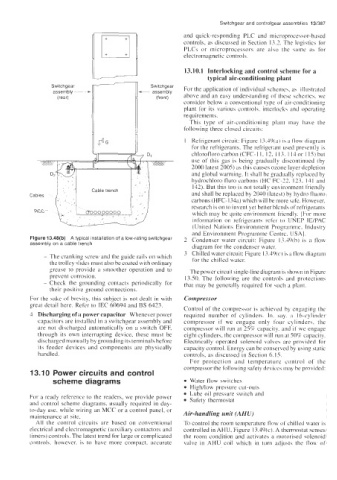
Figure 13.48(b) A typical installation of a low-rating switchgear 2 Condenser water circuit: Figure 13.49(bj is a flow
assembly on a cable trench
diagram for the condcnser water.
- The cranking screw and the guide rails on which 3 Chilled water circuit: Figure I3.49(c) is a flow diagram
thc trolley slides must also be coated with ordinary for the chilled water.
grease to provide a smoother operation and to The power circuit single-line diagram is shown in Figure
prevent corrosion. 13.50. The following are the control\ and protections
- Check the grounding contacts periodically for that may be generally required for wch a plant.
their positive ground connections.
For the sake of brevity, this subject is not dealt in with Compressor
great detail here. Refer to IEC 60694 and BS 6423.
Control of the compressor is achieved by engaging the
4 Discharging of a power capacitor Whenever power required number of cylinders. In. say. a 16-cylinder
capacitors are installed in a switchgear assembly and compressor if we engage only four cylinders;. the
are not discharged automatically on a switch OFF, compressor will run at 25% capacity. and if we engage
through its own interrupting device, these must be eight cylinders, the compressor will run at 50%. capacity.
discharged manually by grounding its terminals hefore Electrically operated solenoid valves are pro\;icled for
its feeder devices and components are physically capacity control. Energy can be conserved by using static
handled controls, as discussed in Section 6.15.
For protection and temperature control of the
compressor the following safety devices may be provided:
13.10 Power circuits and control
scheme diagrams Water flow switches
High/low pressure cut-outs
Lube oil pressure switch and
For a ready reference to the readers, we provide power Safety thermostat
and control scheme diagrams, usually required in day-
to-day use, while wiring an MCC or a control panel, or Air-handling unit (AHU)
maintenance at site.
All the control circuits are based on conventional To control the room temperature flow of chikd water is
electrical and electromagnetic (auxiliary contactors and controlled in AHU, Figure 13.49(c). A thermostat senses
timers) controls. The latest trend for large or complicated the room condition and activates a motorised wlenoid
controls. however. is to have more compact, accurate valve in AHU coil which in turn ad,justs the flow of