
Page 407 - Industrial Power Engineering and Applications Handbook
P. 407
Switchgear and controlgear assemblies 13/381
operation would be dependent on the condition of supply. interrupter are wired in series, as standard practice, by the interrupter
An UN release is generally fitted to trip the interrupting (breaker or MCCB) manufacturers to share the arc energy on a trip
device when the supply ceases and not for any other and enhance contact life, particularly when the control supply is
control schemes. d.c. which is normally the case.
The schemes are logical and simple and have been
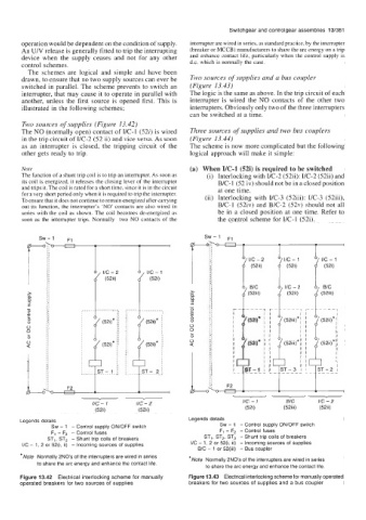
drawn, to ensure that no two supply sources can ever be Two sources of supplies and a bus coupler
switched in parallel. The scheme prevents to switch an (Figure 13.43)
interrupter, that may cause it to operate in parallel with The logic is the same as above. In the trip circuit of each
another, unless the first source is opened first. This is interrupter is wired the NO contacts of the other two
illustrated in the following schemes; interrupters. Obviously only two of the three interrupters
can be switched at a time.
Two sources of supplies (Figure 13.42)
The NO (normally open) contact of I/C-1 (52i) is wired Three sources of supplies and two bus couplers
in the trip circuit of I/C-2 (52 ii) and vice versa. As soon (Figure 13.44)
as an interrupter is closed, the tripping circuit of the The scheme is now more complicated but the following
other gets ready to trip. logical approach will make it simple:
Note (a) When YC-1 (52i) is required to be switched
The function of a shunt trip coil is to trip an interrupter. As soon as (i) Interlocking with I/C-2 (52ii): I/C-2 (52ii) and
its coil is energized, it releases the closing lever of the interrupter B/C- 1 (52 iv) should not be in a closed position
and trips it. The coil is rated for a short time, since it is in the circuit at one time.
for a very short period only when it is required to trip the interrupter. (ii) Interlocking with VC-3 (52iii): I/C-3 (52iii),
To ensure that it does not continue to remain energized after carrying
out its function, the interrupter’s ‘NO’ contacts are also wired in B/C-1 (52iv) and B/C-2 (52v) should not all
series with the coil as shown. The coil becomes de-energized as be in a closed position at one time. Refer to
soon as the interrupter trips. Normally two NO contacts of the the control scheme for I/C-1 (52i).
IIC - 2 l/;G)l f I/C - 1
(52ii) (52i)
, I/C - 2 A, I/C - 1
(52ii)
BIC
(52iii) (52iii)
1 B/c
-
-
. . -. . .
(52i)* (52i)*
I
(52i)* (52i)*
I
I
1 I
1 1 I
L___--
I/C - 1 I/C - 2 IIC - 1 BIC I/C - 2
(52i) (52ii) (52i) (52iii) (52ii)
Legends details Legends details
Sw - 1 - Control supply ON/OFF switch Sw - 1 - Control supply ONIOFF switch
F1 - F2 - Control fuses F1 - F2 - Control fuses
ST,, ST2 - Shunt trip coils of breakers ST1, ST,, ST3 - Shunt trip coils of breakers
I/C - 1, 2 or 52(i, ii) - Incoming sources of supplies I/C - 1, 2 or 52(i, ii) - Incoming sources of supplies
BIC - 1 or 52(iii) - Bus coupler
*Note Normally 2NOs of the interrupters are wired in series *Note Normally 2NOs of the interrupters are wired in series
to share the arc energy and enhance the contact life.
to share the arc energy and enhance the contact life.
Figure 13.42 Electrical interlocking scheme for manually Figure 13.43 Electrical interlocking scheme for manually operated
operated breakers for two sources of supplies breakers for two sources of supplies and a bus coupler