
Page 440 - Industrial Power Engineering and Applications Handbook
P. 440
13/414 Industrial Power Engineering and Applications Handbook
1 Pre-treatment area Acid fumes can be controlled 2 Painting area (applicable to liquid paints)
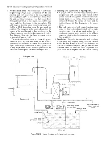
by providing exhaust ducts (lip suction) on the acid A spray booth can be installed as discussed above
pickling tank with a scrubber in the exhaust pipe as and provided with a running-water curtain system
shown in Figure A13.1 to absorb the acid fumes from and an exhaust arrangement to absorb the overs-
the tank and its surroundings. This then passes them prayed paint and its fumes. The paint fumes are
through the scrubber, to have them dissolved in soda circulated through the curtain of water and the
water and then discharged to the atmosphere. The harmless fumes are then discharged to the atmos-
acid fumes with soda water become converted into phere.
HzSOJ or HCl, depending upon the acid used for The wash water mixed with paint which is a strong
pickling. The saturated soda water collected at the waste can be transferred (periodically, if the water
bottom of the scrubber unit is then transferred to the curtain system is a closed cycle rather than a
effluent treatment plant for further treatment. A typical continuous running water system) to the effluent
flow diagram illustrating the fume treatment system treatment plant for further treatment, as shown in
is shown in Figure AI 3.10. Figure A13.12.
The wash water and the spent acid from all the pre- 3 Ventilation The paint shop must be well ventilated
treatment tanks is also transferred to the effluent and provided with exhaust fans to circulate fresh air
treatment plant for further treatment. Spent passivation within the shop. Roughly 20 to 30 air discharges per
liquor from the passivation tank is a strong waste and hour are considered adequate. Wet-painted surfaces,
it may be provided with a separate pipeline to the however, must be protected from suspended dust
effluent treatment plant, as shown in Figure A13.12. particles in the atmosphere and this can be done by
Soda water inlet Clean air Clean air
u
k5-29
4
Fumes
7 I Ti effluent treatment
Scrubber unit
3
Flow control
Saturated water to
(pH value 9-10.5)
Figure A13.10 Typical flow diagram for fume treatment system