Page 581 - Industrial Power Engineering and Applications Handbook
P. 581

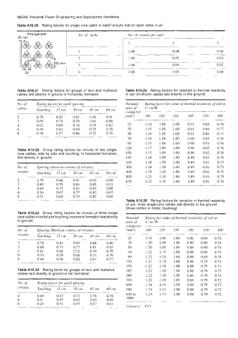
Arrangement           No. of  racks        No. of  circuits per rack
           pJ&      &                                                      2                  3
         25 mm
           &,&       + i.          1                    1 .oo              0.98              .~
                                                                                              0.96
         i &&                      2                    I .oo        .     0.95               0.93
                                                        1 .oo
                                                                                              0.92
                                                                           0.94
                                   3
                                                        1 .oo
            2d                1    6                                       0.93               0.90

        Table A16.21  Rating factors for  groups of  twin and multicore   Table A16.25  Rating factors for variation in thermal resistivity
        cables laid directly in ground in horizontal formation   of soil (multicore cables laid directly in the ground)

        No.  of   Rating factor for axial spacing      Nominal   Rating factor for value of  thermal resistivity of soil in
                                                 .~
                 Touching   15cm   30 cm   45 cm   60cm   area of   C cm/W
                                                       conductor
            ~~
         2       0.79    0.82   0.87    0.90   0.91    (mm’)    100   120   150   200   250   300
         3       0.69    0.75   0.79    0.83   0.86
         4       0.62    0.69   0.74    0.79   0.82     25      1.14   1.08   1.00   0.91   0.84   0.78
         6       0.54    0.61   0.69    0.75   0.78     35      1.15   1.08   1.00   0.9 1   0.84   0.77
         8       0.50    0.57   0.66    0.72   0.76     50      1.15   1.08   1.00   0.9 1   0.84   0.77
                                                        70      1.15   1.08   1.00   0.90   0.83   0.76
                                                        95      1.15   1.08   1.00   0.90   0.83   0.76
                                                       120      1.17   1.09   1.00   0.90   0.82   0.76
         Table A16.22  Group  rating factors  for  circuits  of  two  single-
         core cables, side by side and touching, in horizontal formation,   150   1.17   1.09   1.00   0.90   0.82   0.76
         laid directly in ground                       185      1.18   1.09   1.00   0.89   0.81   0.75
                                                       240      1.18   1.09   1.00   0.89   0.81   0.75
         No. of   Spacing  (between centres of  circuits)   300   1.18   1.09   1.00   0.89   0.81   0.75
         circuits   Touching   15 cm   30 cm   45 cm   60 cm   400   1.19   1.10   1.00   0.89   0.81   0.75
                                                       500      1.21   1.10   1.00   0.89   0.81   0.75
         2       0.79    0.86    0.91   0.93   0.95    630      1.22   1.10   1.00   0.89   0.81   0.74
         3       0.69    0.78    0.84   0.88   0.91    ~~      ~~
         4       0.64    0.73    0.81   0.86   0.88
         6       0.56    0.67    0.77   0.83   0.87
         8       0.51    0.65    0.75   0.82   0.86
                                                       Table A16.26  Rating factors for variation in thermal resistivity
                                                       of  soil, three single-core cables laid directly in the ground
                                                       (three cables in trefoil, touching)
         Table A16.23  Group  rating factors for  circuits  of  three single
         core cables in trefoil and touching, horizontal formation laid directly   Nominal   Rating for value of  thermal resistivity of  soil in
         in ground                                     area of   C cm/W
                                                       conductor
         No. of   Spucing  (Between centres of circuits)   (mm’)   100   120   150   200   250   300
         circuits   Touching   15 cm   30 ern   45 ern   60 cm
                                                        25      1.19   1.09   1.00   0.88   0.80   0.74
         2       0.78     0.81   0.85   0.88   0.90     35      1.20   1.09   1.00   0.88   0.80   0.74
         3       0.68     0.71   0.77   0.81   0.83     50      1.20   1.09   1.00   0.88   0.80   0.74
         4       0.61    0.65    0.72   0.76   0.79     70      1.21   1.10   1.00   0.88   0.80   0.74
         6       0.53     0.58   0.66   0.71   0.76     95      1.22   1.10   1.00   0.88   0.80   0.74
         8       0 48     0.54   0.62   0.67   0.72
                                                        I20     1.22   1.10   1.00   0.88   0.79   0.74
                                                        150     1.22   1.10   1.00   0.88   0.79   0.73
         Table A16.24  Rating factor for groups of  twin and multicore   185   1.22   1.10   1.00   0.88   0.79   0.73
         cables laid directly in ground in tier formation
                                                       240      1.22   1.10   1.00   0.88   0.79   0.73
                                                       300      1.22   1.10   1.00   0.88   0.79   0.72
         No. of   Rating factor for axial spacing
                                                 .~    400      1.24   1.11   1.00   0.88   0.79   0.72
         circuits   Touching   15 cm   30 cm   45 cm   60 cm   500   1.24   1.11   1.00   0.88   0.79   0.72
         4       0.60     0.67   0.73   0.76   0.78    630 to   1.24   1.11   1.00   0.88   0.79   0.72
         6       0.51     0.57   0.63   0.67   0.69     1000
         8       0.45     0.51   0.57   0.57   0.61
                                                        Courtesy:  CCI
   576   577   578   579   580   581   582   583   584   585   586