
Page 579 - Industrial Power Engineering and Applications Handbook
P. 579
16/544 Industrial Power Engineering and Applications Handbook
A16.2 Technical details 39 supply HT or LT at
receiving end. [This
We have reproduced in a few Tables (A16.3-A16.15) voltage may be lower
for cables that are used more com-monly in all voltage than rated because of
ratings and with aluminium conductors. For other cables distribution drops]
and copper conductor cables, refer to the manufacturers
of their catalogues. Transformer (if
Voltage at this the receiving end
A16.3 Service conditions point is subject supply is HT)
to drops from
The standard parameters of installation on which the receiving point
ratings of the cables are based as in the previous tables, up to this point
are noted in Table A16.16.
Table A16.16 Standard service conditions
Parameter PVC PILC XLPE
~ _ _ _
Ground temperature OC 30 30 30
Ambient air temperature "C 40 40 40
Depth of laying in ground
Up to 1.1 kV crn 15 - -
3.3 to 11 kV cm 90 90 90
22 and 33 kV cm - 105 105
Thermal resistivity of soil,
"C c m 150 150 150
Thermal resistivity of cable
insulation, "C c m 650 550 350
A16.4 Recommended derating factors
These are common for all types and sizes of cables,
except where noted. Derating of cable ratings resulting
from site conditions and laying parameters are provided
in Tables A16.17-A16.26.
A16.5 Voltage drop
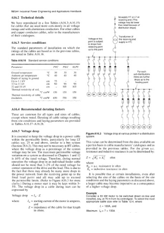
Figure A16.3 Voltage drop at various points in a distribution
It is essential to keep the voltage drop in a power cable system
within the permissible limits, particularly for long LT
cables say, 25 m and above, similar to a bus system This value can be determined from the data available on
(Section 28.6.2). This may not be necessary in HT cables, a per km basis in cable manufacturers' catalogues and as
where the voltage drop as a percentage of the system provided in the previous tables. For the given a.c.
voltage may be low. The maximum permissible voltage resistance and inductive reactance it can be determined by:
variation on a system as discussed in Chapters 1 and 12
is +6% of the rated voltage. Therefore, during normal Z = ,/RZc + X: ohm
operation the voltage drop in an individual feeder cable where
should not be more than I-2% of the rated voltage for R,, = 8.c. rcsistance in ohm
correct operation of the drive and the load. This is due to X, = inductive reactance in ohm
the fact that there may already be many more drops in
the power network from the receiving point up to the It is possible that at certain installations, even after
final load point and all may add up to exceed selecting the size of the cables on the basis of the site
the permissible limits. (Refer to Figure A16.3 for more conditions and the laying parameters as discussed above,
clarity.) During a motor start it may be kept within 3- a larger cable may become imperative as a consequence
5%. The voltage drop in a cable during start can be of a higher voltage drop.
expressed by
Example
Voltage drop = I,, . Z Consider a 55 kW motor to be switched direct on-line and
installed, say, at 75 m from its controlgear. To select the most
where Z,, = starting current of the motor in amperes, appropriate cable size refer to Table 12.4, where
and
Z = impedance of the cable for that length /r = 100A, and
in ohms. Maximum ISt = 7 x 1 OOA