
Page 582 - Industrial Power Engineering and Applications Handbook
P. 582
Captive (emergency) power generation 161547
and the voltage drop during start
= 7 x 100 x 0.394 x 3
volts
1000
= 20.7 V
which is still almost 5% of a 415 V system and is again, only .mm.
marginally suitable for such an application. For still greater
length of feeder cable line, a yet higher size of cable may be
needed but such lengths are seldom required.
A16.6 Skin and proximity effects in a
multicore cable
The influence of skin effects in a multi-core cable is
almost the same as that of a multiphase busbar system,
discussed in Sections 28.7 and 28.8. However, unlike a
busbar system, the resistance and inductive reactance
for various sizes of cables can be easily measured and
are providcd by leading manufacturers as standard practice
in their technical data sheets. To this extent, making an
assessment of skin effects in cables is easy compared to
a busbar s stem. Since all the phases in a cable, of a 3-
core or 3$?-core are in a rcgularly twisted formation
throughout the length of the cable, they represent the
case of an ideal phase transposition (Section 28.8.4(3)) Tune seconds (t)
and almost nullify the effect of proximity.
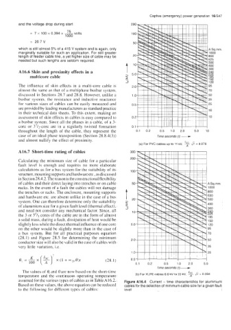
(a) For PVC cables up to 11 kV. % fi = 0.076
A16.7 Short-time rating of cables
Calculating the minimum size of cable for a particular
fault level is enough and requires no more elaborate
calculations as for a bus system for the suitability of its
structure, mounting supports and hardwareetc., as discussed
in Section 28.4.2. Thereason is the constructional flexibility
of cables and their direct laying into trenches or on cable
racks. In the event of a fault the cables will not damage
the trenches or racks. The enclosure, mounting supports
and hardware etc. are absent unlike in the case of a bus
system. One can therefore determine only the suitability
of aluminium size for a given fault level (thermal effect),
and need not consider any mechanical factor. Since, all
the 3 or 3'/2 cores of the cable are in the form of almost
a solid mass, during a fault, dissipation of heat would be
slightly less while the direct thermal influence of one core
on the other would be slightly more than in the case of
a bus system. But for all practical purposes equation
(28.1) and Figure 28.5 for determining the minimum
conductor size will also be valid in the case of cables with
very little variation, i.e.
(28.1)
The values of 0, and 8 are now based on the short-time
temperature and the continuous operating temperature (b) For XLPE cables 6.6 kV to 33 kV. % fi = 0.094
assumed for the various types of cables as in Table A16.2. Figure A16.4 Current - time characteristics for aluminium
Based on these values, the above equation can be reduced cables for the selection of minimum cable size for a given fault
to the following for different types of cables: level