
Page 580 - Industrial Power Engineering and Applications Handbook
P. 580
Captive (emergency) power generation 16/545
:. recommended cable size as in Table 12.4 = 3 x 70 mm2. However, during normal running, 3 x 70 mm* cable will
Considering an armoured cable, as in Table A16.3, a.c. have a voltage drop of just 4.03 V (100 x 0.538 x 75/1000 =
resistancelp hase 4.03 V), which is less than 1% of 415 V. Therefore, depending
R,, = 0.532 - CY1000 m at 70°C upon the duty the motor may have to perform, and other
loads connected on the same bus, the design engineer would
and inductive reactancelphase, X, = 0.083 CY1000 m at 50 Hz. be a better judge to decide whether to select a higher size of
cable or be content with this marginal case.
:. impedance Z = 40.532' + 0.083' For clarity, voltage drop in the next size of cable, i.e. 3 x 95
= 0.538 W1000 m mm', is also calculated as
75
and voltage drop during start = 7 x 100 x 0.538 x - R,, = 0.385 W1000 m at 70°C
1000
= 28.25 V X, = 0.083 CY1000 m at 50 Hz
which is almost 6.8% for a 415V system and is not :.
recommended. This cable size is therefore inadequate for Z= d0.385' + 0.083'
such a feeder length and the next size, Le. 3 x 95 mm2, may
be chosen. = 0.394 C2/1000 m
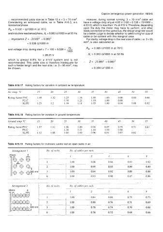
Table A16.17 Rating factors for variation in ambient air temperature
Air temp. "C 15 20 25 30 35 40 45 50 55
Rating factor PVC 1.40 1.32 1.25 1.16 1.09 1 .oo 0.90 0.80 0.68
PILC - - 1.30 1.21 1.10 1 .oo 0.88 - -
XLPE 1.25 1.2 1.16 1.11 1.05 1 .oo 0.94 0.88 0.82
Table A16.18 Rating factors for variation in ground temperature
Ground temp. "C 15 20 25 30 35 40 45 50 55
Rating factor PVC 1.17 1.12 1.06 1 .oo 0.94 0.87 0.79 0.71 0.61
PILC - - 1.30 1.21 1.10 1 .oo 0.88 - -
XLPE 1.12 1.08 1.04 1 .oo 0.96 0.91 0.87 0.82 -
Table A16.19 Rating factors for multicore cables laid on open racks in air
Arrangement 1 No. of racks No. of cables per rack
d
1 2 3 6 9
1 1 .oo 0.98 0.96 0.93 0.92
2 1 .oo 0.95 0.93 0.90 0.89
3 1 .oo 0.94 0.92 0.89 0.88
6 1 .oo 0.93 0.90 0.87 0.86
Arrangement 2 No. of racks No. of cables per rack
2 3 6 9
1 .oo 0.84 0.80 0.75 0.73
2 1 .oo 0.80 0.76 0.71 0.69
3 1.00 0.78 0.74 0.70 0.68
6 1 .oo 0.76 0.72 0.68 0.66