
Page 63 - Industrial Power Engineering and Applications Handbook
P. 63
2/44 Industrial Power Engineering and Applications Handbook
the short-circuit end rings of a squirrel cage rotor melted, and 300%
the molten metal, through its centrifugal force, had hit the
stator overhangs, damaging them through its insulation,
causing an inter-turn fault.
2.7.2 Heating during a no-load start-up
200%
During a no-load start-up, i.c. when the motor shaft is
free, half the energy drawn from the supply appears as f
heat in the rotor and the stator windings. In slip-ring
e
motors the bulk of the rotor heat is shared by the external P)
rcsistance, a feature which makes it a better choice for co
frequent starts and stops, and for driving loads that possess 100%
large inertia. It has been seen that most of the stringent
load requirements can also be met with high torque squirrel
cage motors, manufactured with a judicious design of
stator and rotor resistances, an efficient means of heat
dissipation and a proper choice of active material. The
heat generated during a no-load start-up can be expressed u
by; Speed +
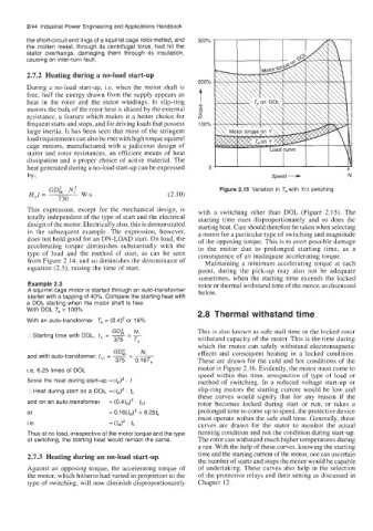
GD; .N: Figure 2.15 Variation in T, with Y/A switching
H,l = w.s (2.10)
730
This expression, except for the mechanical design, is with a switching other than DOL (Figure 2.15). The
totally independent of the type of start and the electrical starting time rises disproportionately and so does the
design of the motor. Electrically also, this is demonstrated starting heat. Care should therefore be taken when selecting
in the subsequent example. The expression, however, a motor for a particular type of switching and magnitude
does not hold good for an ON-LOAD start. On load, the of the opposing torque. This is to avert possible damage
accelerating torque diminishes substantially with the to the motor due to prolonged starting time, as a
type of load and the method of start, as can be seen consequence of an inadequate accelerating torque.
from Figure 2.14, and so diminishes the denominator of Maintaining a minimum accelerating torque at each
equation (2.5), raising the time of start. point, during the pick-up may also not be adequate
sometimes, when the starting time exceeds the locked
Example 2.3 rotor or thermal withstand time of the motor, as discussed
A squirrel cage motor is started through an auto-transformer below.
starter with a tapping of 40%. Compare the starting heat with
a DOL starting when the motor shaft is free.
With DOL T, = 100%
2.8 Thermal withstand time
With an auto-transformer T, = (0.4)' or 16%
GD; N This is also known as safe stall time or the locked rotor
:. Starting time with DOL, t, = -
X-
375 T, withstand capacity of the motor. This is the time during
which the motor can safely withstand electromagnetic
GDi N effects and consequent heating in a locked condition.
and with auto-transformer, t,, = - -
x
375 O.16Ta These are drawn for the cold and hot conditions of the
Le. 6.25 times of DOL motor in Figure 2.16. Evidently, the motor must come to
speed within this time, irrespective of type of load or
Since the heat during start-up -(/,J2 . f method of switching. In a reduced voltage start-up or
:. Heat during start on a DOL =(Ist)' . t, slip-ring motors the starting current would be low and
these curves would signify that for any reason if the
and on an auto-transformer = (0.4/,# . t,~ rotor becomes locked during start or run, or takes a
or ~0.16(/,,)' x 6.25tS prolonged time to come up to speed, the protective device
must operate within the safe stall time. Generally, these
i.e. = (kl)' ' ts curves are drawn for the stator to monitor the actual
Thus at no load, irrespective of the motor torque and the type running condition and not the condition during start-up.
of switching, the starting heat would remain the same. The rotor can withstand much higher temperatures during
a run. With the help of these curves, knowing the starting
2.7.3 Heating during an on-load start-up time and the starting current of the motor, one can ascertain
the number of starts and stops the motor would be capable
Against an opposing torque, the accelerating torque of of undertaking. These curves also help in the selection
the motor, which hitherto had varied in proportion to the of the protective relays and their setting as discussed in
type of switching, will now diminish disproportionately Chapter 12.