
Page 64 - Industrial Power Engineering and Applications Handbook
P. 64
Motor torque, load torque and selection of motors 2/45
C = heat capacity of the motor
J- Locked rotor current = heat required to raise the temperature of the
I I windings by 1 "C in Joules
= w.
6
where
W = weight of the stator windings in kg
= volume of stator windings x specific gravity of
the metal of the windings
= L,, . Z, . A,, . d
Ln,t = length of a mean turn of the winding in metres
Z, = number of stator turns per phase
A,, = area of the whole windings in cm'
d = specific gravity of the winding material in
gm/cm3
6 = specific heat of winding metal in watt . s/kg m "C
I i Nore I In equation (2.11) it is presumed that the heating of the
windings is adiabatic Le. whatever heat is generated during a stalled
condition IS totally consumed in raising the temperature of the
stator windings by 8. An adiabatic process means that there is no
Safe stall time 'tS; (seconds)- heat transfer from the system to the surroundings. This is also
known as the heat sink process. The presumption is logical. hecause
- c- the duration of heating is too short to be able to dissipate a part of
D-- . ----cI it 10 other parts of the machine or the surroundings.
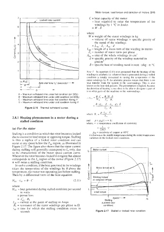
A - Maximum withstand time under hot condition (on DOL)
B - Maximum withstand time under cold condition (on DOL)
C - Maximum withstand time under hot condition during Y
D - Maximum withstand time under cold condition during Y
Figure 2.16 Thermal withstand curves
2.8.1 Heating phenomenon in a motor during a
stalled condition and p = pJ0( 1 + - h)
where, = = temperature coefficient of resistivity
1
(a) For the stator - 234.5 "C
p4" = resistivity of copper at 40°C
Stalling is a condition in which the rotor becomes locked It is known as the middle temperature during the entire temperature
due to excessive load torque or opposing torque. Stalling variation in the locked rotor condition.
is thus a replica of a locked rolor condition arid can
occur at any speed below the Tpo region, as illustrated in
Figure 2.17. The figure also shows that the stator current
during stalling will generally correspond to I,, only, due
to the characteristic of the motor speed-current curve.
Whenever the rotor becomes locked in a region that almost
corresponds to the I,, region of the motor (Figure 2.17)
it will mean a stalling condition.
In such a condition, if the heat generated in the windings
raises the temperature of the windings by 8 above the
temperature, the motor was operating just before stalling.
Then by a differential form of the heat equation:
where
HstI =heat generated during stalled condition per second
in watts I Load torque ~ I
= power loss
I
= 1\21, RI Stalling Speed --F
= current at the point of stalling in Amps (Locked rotor
Rf = resistance of the stator windings per phase in R condition)
tSti = time for which the stalling condition exists in
seconds Figure 2.17 Stalled or locked rotor condition