Page 658 - Industrial Power Engineering and Applications Handbook
P. 658

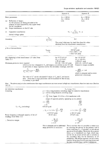
Surge arresters: application and selection  181623


                                                             Segment A          Segment B
      Basic parameters                                      Z,,  = 300 R       Zsl = 300
                                                            Zsz = 300 R         Z,,  = 40 R
      (a)  Reflection of surges:                            Low                 Low
          As the arresters are being provided at the
          primary of each transformer, this aspect need
          not be considered
      (b)   Surge transferences to the LV side
      (i)  Capacitive transference
          (initial voltage spike)

                                                CP
      Assuming                                                           0.4
                                              cp + cs
                                                       The actual value may be much less than this when
                                                       obtained from the transformer manufacturer
      p  for a YlA transformer                                           1.15
                                             Vt(F0W)                  945 kV peak
                                              :.  v,,               = 0.4 x 945 x  1.15
                                                                    = 434.7 kV peak
      BIL (lightning) of the transformers’ LV sides from   for 15.75 kV LV   for 132 kV LV
      Table 13.2                                       (V,  = 17.5 kV)    (V,  = 145 kV)
                                                       = 95 kV peak       = 650 kV  peak
      Minimum protective level required                9511.05  = 90.5 kV peak   650/1.05 = 619 kV peak
                       which is too low compared to VI, and requires an arrester on the LV  side   Protective margin available
                       or provision of  surge capacitors across the secondary windings, such that
                                                                          -
                           cp     <- 90.5                                 _-2 650   1.49
                               C‘
                        c,  + c,  i   434.7                                 474.7
                                                                          whichis adequate and no more
                                                                          protection is necessary
                       The value of C’ can be calculated if values of  C,  and C,  are known.
                       Note  Even then a surge protection will be essential for the tertiary,
                       if a tertiary is provided.
      Note  The above analysis also corroborates that surge transferences are more severe in high ratio transformers than low ratio ones (Section
      18.5.2)
      (ii) Inductive transference                               Vti = p.9.r. VJn
      Assuming                            p  = 1 for a long-duration switching surge for inductive transference
                                           q = 1.8 for a long-duration switching surge
                                              Jr
                                           r = - from Figure 18.14 for a YIA transformer with
                                               2
                                              surges of opposite polarity appearing on two phases
                                              420
                                                                              420
                                           n= -                              -
                                              17.5                            145
                                            = 24                             = 2.9
                 VI = V,,  (switching)     676 kV peak
                                                       &  676         =lX1.8X-X- &  676
                                                          x
                                           :.  vti = 1 x  1.8 x - -
                                                        2   24                2   2.9
                                               = 43.9  kV peak       = 363 kV peak
      Power frequency withstand capacity of the LV   38 kV r.m.s.    275 kV r.m.s
      windings from Table 13.2
                                                     38 fi                --
                                                                            275 -,h
                                                   -
       :.  Protective margin                       --                     -
                                                      43.9                    363
                                                   = 1.22                 = 1.07
                                           This is adequate and no additional  This is too low. But it is possible to make it up
                                           surge protection is necessary   by  selecting the arrester at the primary with a
                                                                  lower switching V,,,,  if possible, or provide an
                                                                  arrester at the secondary. Moreover, the response
                                                                  factor, q, is considered very  high, which may
                                                                  not be true in actual service and an arrester at
                                                                  the  secondary may  not  be  necessary  in  all
                                                                  probability. The design engineer can use a more
                                                                  realistic factor based on his past experience and
                                                                  the data available from similar installations.
   653   654   655   656   657   658   659   660   661   662   663