Page 656 - Industrial Power Engineering and Applications Handbook
P. 656
Surge arresters: application and selection  18/621
         Notes                                                = 269 R
            The above selection of the arrester may be considered   2.T  = 2800~~
            as having taken account of  reflections at the terminals.
            When  such  an  arrester  is  installed  on  the  system,  it
            takes care of switching, lightning or steep to very steep   Note
            rising surges, irrespective of their amplitudes.   The time of travel from the point the lightning strikes on the
            It is presumed that the protective distance (distance of   overhead  lines to the  arrester, considering  a line  length of
            the protected equipment from the arrester) is short and   approximately 420 km and speed of propagation of the surge
            within safe limits. It too must be checked before a final   as 0.3 km/,us,
            selection of the arrester, as explained in Section 18.6.2.   T=  ~  420   = 1400 PS
            The above selection, however, seems to be appropriate   0.3
            for a distance up to 8-10  m as considered in Example   Accounting for reflections, the total time must be considered
            18.4.                                      as 2 x  1400 or 2800 ps. Accordingly, 2800 ps is specified by
            The  arrester  selected  has  protective  margins  much   IEC 60099-4  for the testing of the arrester under the worst
            greater  than  the  minimum  required.  In  fact  even   conditions.  The  arrester  must  also  have  the  capability  to
            considering a protective distance up to 8-10  m, it would   successfully  discharge  the  prospective  surge  under  such
            be possible to select the  arrester with the  next higher   conditions.
            V,,   to enhance the life of the arrester without jeopardizing
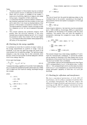
            the safety of the equipment.               :.  w =  (874 - 654)  x 654 x 2800 x   kJ
                                                                269
         (B) Checking for the energy capability
                                                           _- 220  x 654 x 2800 x
                                                           -
         It is sufficient to check this for systems of range II alone, as   269
        the  energy  requirements  for  systems  of  range  I  may  be
         moderate,  since  now the  lightning  surges  are found  to  be   = 1498 kJ or  ~ 1498 = 4.46 kJ/kV,
                                                                     336
         more severe than the switching surges. The lightning surges
         dissipate  a  very  low  energy  due  to  their  extremely  short   The arrester chosen has a total energy capability of 7 kJ/kVr
        duration, while a normal arrester would be adequate to absorb   (from the manufacturer’s catalogue).  In service the arrester
         much more energy than this.                   will be required to discharge much less energy than this as
                                                       the distance of the arrester from the point of surge origination
         W (for each discharge)
                                                       may be much smaller than considered.
                                                         Line arrester class can also be selected quickly from Figure
                                              (1 8.10)
                                                       18.23, corresponding to Vres/Vr. In the above case, it is 654/
        To assess the energy capability of the arrester more realistically,   336, i.e. 1.95, corresponding to which also the class of arrester
         let us consider the established system parameters as in Table   works out as ‘4’, as considered by us, and which will have an
         18.6 to determine  the  maximum energy  discharge through   energy  absorption  capability  of  more  than  4.5  kJ/kVr per
        the arrester,                                  discharge.
        where
                                                       (C) Checking for reflections  and transferences
             Vt  = 2.6  V,
                                                       We  have  considered  protection  of  both  400  kV
                = 2.6 x 336
                                                       transformers, one for primary transmission and the other
                = 874 kV                               for  secondary  transmission.  We  will  now  analyse  the
                                                       influence of surge reflections and transferences of a surge
            V,,,   = 654 kV (for I,  = 1 kA)
                                                       occurring on the  400 kV  primary  transmission  bus  as
             Z,  = 0.8Vr                               shown in Figure 18.25 and its effects on segments A and
                = 0.8 x 336                            B.

