
Page 651 - Industrial Power Engineering and Applications Handbook
P. 651
18/61 6 Industrial Power Engineering and Applications Handbook
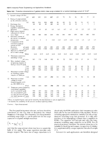
Table 18.9 Protective characteristics of gapless station class surge arresters for a nominal discharge current of 10 kAa
1 System voltage (50 Hz)
kV 420 245 245 I45 123 72 36 36 24 12 12
2 Rating of surge arrester
(at the reference current)
kV 390 216 198 220 96 60 36 30 18 12 9
3 Discharge class 111 111 111 III I11 I1 I1 11 I I I
4 Energy dissipation
capability cumulative
operation (UkV,) IO 10 IO 6.5 6.5 4.5 4.5 4.5 2.5 2.5 2.5
5b High current impulse
withstand of 4/10 ps
wave shape kA 100 100 100 100 100 100 100 100 100 100 100
6 Reference current of
the arrester at ambient
ternperalure mA 5 5 5 3.25 3.25 2.25 2.25 2.25 1.5 1.5 1.5
7 Components of the
continuous leakage
current at COV
Resistive pA peak 400 400 400 400 400 400 400 400 400 400 400
Capacitive pA peak 1500 1500 1500 1500 1500 1500 1500 1500 1500 1500 1500
8 Watt loss at MCOV per
kV of rated voltage
WkA 0.25 0.25 0.25 0.25 0.25 0.25 0.25 0.25 0.25 0.25 0.25
9 Maximum continuous
operating voltage
kV r.m.s. 303 178 168 102 81 52 30.5 25.5 15 IO 7.65
10 Max. residual voltage
at lightning impulse of
8/20 ,us wave kV peak
5 kA 860 567 518 333 249 162 103 85 60 38 33
10 kA 900 602 550 355 264 175 110 90 65 40 35
20 kA 957 668 610 390 304 202 I28 104 75 46 41
11 Maximum residual voltage
at switching current
impulse of 30/60 ps,
I kA 780 496 457 294 221 138 87 71 52 32 28
12 Maximum residual
voltage at steep-
fronted impulse (1/20
ps, IEC 60099-4) at
10 kA 1050 654 600 386 288 202 124 101 73 45 40
13 Temporary power frequency
overvoltage capability
(a) 0.1 second kV peak 705 397 364 220 156 97 58 48 29 19 14
(b) 1.0 second kV peak 580 382 350 212 149 93 56 46 28 18 14
(c) 10.0 seconds kV peak 565 367 336 203 142 89 53 44 26 17 13
(d) 100.0 seconds kV peak 550 305 280 169 135 84 51 42 25 16 12
~~ ~ ~~
a These are typical figures and can be varied by the manufacturer to suit an application
To identify the suitability of the arrester on direct lightning strikes.
Courtesy Elpro International
The first peak being more relevant, we have therefore absorb only the FOWs and reduce their steepness to make
considered it’s the rise time to determine the virtual them safe for the turn insulation of the machine. When a
frequency of the surge. This frequency, for a long-duration switching operation commences, initially it is only along-
switching surge (high t,), can be quite low for the surge duration switching surge that generates. It is only after
capacitor to acquire enough reactance restrikes of the interrupting contacts that it amplifies to
FOWs. The capacitor will activate only after the long-
duration switching surge amplifies to an FOW. For all
practical purposes, therefore, the arrester alone has to be
suitable for handling such surges, irrespective of whether
such that the surge arrester alone may have to sustain the it is supplemented by a surge capacitor. See also Example
bulk of the surge. The surge capacitor provides only 17.5.
meagre support. The basic use of surge capacitors is to Arresters for such applications are therefore designed