
Page 648 - Industrial Power Engineering and Applications Handbook
P. 648
Surge arresters: application and selection 18/61 3
be considered as three consecutive discharges for
all practical purposes. It is, however, seen that in
service, even two consecutive discharges are rare
and three may never occur. It is, therefore, sufficient
to consider two consecutive discharges for selecting
an arrester. The normal practice by leading
manufacturers is to specify only the total energy
Class
capability for which their arresters would be
\\ I suitable during consecutive discharges.
Apparently a higher level of V,,, would mean a lower
level of energy absorption by the surge arrester in terms
of V,. For an excessive level of W required, it is better to
select a higher V,. If it jeopardizes the required protection
level, then select another type of surge arrester with a
higher energy capability.
To determine W from the above it is essential to know
VreJ v, -
1 3 3.5 the system parameters. Based on system studies of
different voltage systems (transmission lines particularly)
1.95 many data have been collected. Typical data as suggested
by IEC 60099-4 are provided in Table 18.6 for a general
reference. For secondary transmission or primary distri-
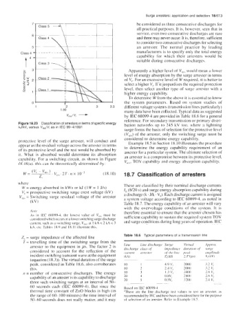
Figure 18.23 Classification of arresters in terms of specific energy bution networks up to 245 kV too. where a lightning
kJ/kV, versus V,,,/V, as in IEC 99-4/1991
surge forms the basis of selection for the protective level
(VTe5j of the arrester, only the switching surge must be
considered to determine energy capability.
protective level of the surge arrester, will conduct and Example 18.5 in Section 18.10 illustrates the procedure
appear as the residual voltage across the arrester in terms to determine the energy capability requirement of an
of its protective level and the rest would be absorbed by arrester for a particular system. The ultimate selection of
it. What is absorbed would determine its absorption
capability. For a switching circuit, as shown in Figure an arrester is a compromise between its protective level,
V,,, TOV capability and energy absorption capability.
18.18(a). this can be theoretically determined by:
( 1 8. 10) 18.7 Classification of arresters
where These are classified by their nominal discharge currents
W = energy absorbed in kWs or kJ (1 W = I J/s) I, (8120 s) and surge energy absorption capability during
V, = prospective switching surge crest voltage (kV)
V,.,, = Switching surge residual voltage of the arrester a discharge (k . J/k . V,j. Each discharge current is assigned
a system voltage according to IEC 60099-4, as noted in
(kV) Table 18.7. The energy capability of an arrester will vary
with the overvoltage conditions of the system. It is
N0tp therefore essential to ensure that the arrester chosen has
As in IEC 60099-4. the lowest value of Vrcb must he sufficient capability to sustain the required system TOV
considered which occurs at a lower switching surge discharge and surge conditions during long years of operation. IEC
current. such as a switching surge, V,,,. at 1 kA < 2 kA < 3
hA. etc. Tahles 18.9 and 18.1 I illustrate this.
Z, = surge impedance of the affected line Table 18.6 Typical parameters of a transmission line
T = travelling time of the switching surge from the
arrester to the equipment in ,us. The factor 2 is Line Line dischurgr
considered to account for the reflection of the discharge cluss of
iirrester
current
incident switching transient wave at the equipment (kA 1
(equation (18.3)). The virtual duration of the surge ~~ ~
peak. considered in Table 18.6, also corroborates I 0 1
this. IO 2
PI = number of consecutive discharges. The energy 10 3
capability of an arrester is its capability to discharge 20 4
three such switching surges at an interval of 50- 20 S
60 seconds each (IEC 60099-4). But since the Based on IEC 60099-4
thermal time constant of ZnO blocks is high (in 'These are the line discharge test values to test an arrester. as
the range of 60- I00 minutes) the time interval of recommended by IEC and have been considered here lor the purpose
50-60 seconds does not really matter, and it may of selection of an arrester. Refcr to Example 18.5.