
Page 646 - Industrial Power Engineering and Applications Handbook
P. 646
Surge arresters: application and selection 18/61 1
overhead line. and are also reasonably shielded by the and the working gap required between the mounting of
line transformer, switchgear and cables. Switchgear and the arrester and the protected equipment. On the occu-
the bus systems, which may or may not be as shielded as rrence of a voltage surge, while the arrester will conduct
the motors, have comparatively a higher BIL than a motor. and absorb the part of surge voltage that is in excess of
Their prescribed impulse withstand level for more exposed its protective level (V,.,,), the residual voltage, V,.,,, will
installations is given in Table13.2. list I1 or 111, while for travel ahead with the same steepness (r.r.r.v.) until it
shielded installations, it is lower and given in list I. One reaches the equipment under protection. It may regain a
may notice that list I is still higher than a motor. On this sufficient surge voltage to endanger the BIL of the
BIL is considered a suitable protective margin to provide equipment. Since the voltage will continue to rise as it
sufficient safety to the protected equipment as in Table travels ahead, as illustrated in Figure 18.22, the equipment
18.7. will be subject to higher stresses than the protective level
considered for the surge arrester. The distance between
Protective characteristics of an arrester arrester and the equipment and the r.r.r.v. will determine
the excess stress to which the equipment will be subject.
The protective characteristic of a surge arrester is defined This can be determined by
by its V,.,,, as a function of its nominal current (I,) and
the time of rise, t,. in the impulse region as noted above. V, = V,,, + S.2.T ( 18.9)
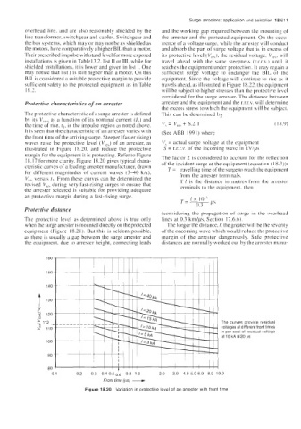
It is seen that the characteristic of an arrester varies with (See ABB 199 1 ) where
the front time of the arriving surge. Steeper (faster rising)
waves raise the protective level (Vres) of an arrester, as V, = actual surge voltage at the equipment
illustrated in Figure 18.20. and reduce the protective S = r.r.r.v. of the incoming wave in kVlp
margin for the equipment it is protecting. Refer to Figure The factor 2 is considered to account for the reflection
18.17 for more clarity. Figure 18.20 gives typical chara-
cteristic curves of a leading arrester manufacturer, drawn of the incident surge at the equipment (equation ( 18.3)):
for different magnitudes of current waves (340 kA), T = travelling time of the surge to reach the equipment
from the arrester terminals.
V,,, versus t,. From these curves can be determined the If 1 is the distance in metres from the arrester
revised V,.,, during very fast-rising surges to ensure that terminals to the equipment, then
the arrester selected is suitable for providing adequate
an protective margin during a fast-rising surge.
Protective distance
(considering the propagation of surge in the overhead
The protective level as determined above is true only lines at 0.3 kmlys, Section 17.6.6).
when the surge arrester is mounted directly on the protected The longer the distance, I, the greater will be the severity
equipment (Figure 18.21). But this is seldom possible, of the oncoming wave which would reduce the protective
as ther-e is usually a gap between the surge arrester and margin of the arrester dangerously. Safe protective
the equipment, due to arrester height, connecting leads distances are normally worked out by the arrester manu-
The curves provide residual
voltages at different front times
in per cent of residual voltage
at 10 kA 8/20 us
Front time (ps) -
1
0.1 0.2 0.3 0.4 0.5 0.6 0.8 1.0 2.0 3.0 4.0 5.0 6.0 8.0 10.0
Figure 18.20 Variation in protective level of an arrester with front time