
Page 643 - Industrial Power Engineering and Applications Handbook
P. 643
18/608 Industrial Power Engineering and Applications Handbook
Table 18.5 Determining TOV
TOVs Cause of TOV OVjactor Tripping time TOVfacror Kyrom Figure 18 16(b) for a
purticular brand of surge arrester
~~ ~
~
TOV," Ground fault
(i) for a solidly grounded system 5 1.4 1 or 3 seconds 1.16 - for 1 second
I. I3 - for 3 seconds
(ii) For an isolated neutral system 1.73 IO seconds to a few 1.1 ~ for IO seconds
hours and more 0.93 ~ for 2 hours
TOV, Load rejection 1.1 1 second 1.16
TOV," Phase-to-phase fault h 1 or 3 seconds 1.16-forlsecond
1.13 - for 3 seconds
"Consider only one eventuality to occur at a time.
bA phase-to-phase fault is a transient condition and may give rise to TRVs in the healthy phase. Such a situation may exist for one to three
seconds, depending upon the protection scheme adopted. It is a long-duration condition for a surge arrester. Such an occurrence may be rare
and need not be considered if the GF condition is already taken into account. However, for the sake of accountability, the voltage rise in
the healthy phase under such a fault condition may be considered similar to the first pole-clearing condition of a circuit breaker. Although
it may not be appropriate to equate the two conditions, the magnitude of overvoltage may fall in a similar range. IEC 60056 has suggested
the following TRVs across the first pole during a brcaker-opening sequence, while the other two poles are still in a cluaed condition:
up to 72.5 kV 1.3 V,
100-170 kV 1.3-1.5 V,
245 kV and above 1.3 V,
(V, being the rated voltage of the system)
The overvoltage factor, due to a phase fault, may thus not exceed a ground fault (GF) condition. It would, therefore, be appropriate to
consider the GF condition instead of a phase fault and, in all probability, it will be adequate to account for this contingency.
Duration: This will depend upon the ground fault and minimum rated voltage V,, = 243/0.8 = 304 kV, when the
protection scheme adopted and may be considered as system is not subject to any TOV. Consider a solidly grounded
follows: system, with a protective scheme of 3 seconds and the
(a) For a solidly grounded system: 1-3 seconds (nor- eventuality of load rejection, which may occur simultaneously:
mally, generation and transmission systems are :. Total TOV = 1.4 x 1.1 = 1.54
provided with a longer tripping time of up to 3 From Figure l8.16(b), the TOV factor, K= 1.13 for 3-second
seconds, and a distribution system still longer, say, tripping.
up to 10 seconds). 243
(b) For an isolated, impedance or resonant grounded :. Required V, = 1.54
1.13
system: from a few minutes to several hours (when = 331 kV (which is higher than 304 kV)
it is 2 hours or more, it may be considered conti-
nuous for the purpose of selection of an arrester).
Short-circuit condition (Section 13.4.1(6)).
Based on these discussions and experience from diffe-
rent installations, the likely power frequency overvoltage t
(TOV) over a long period of operation for different voltage
systems can be determined. For a more accurate value at
a particular installation, it is advisable to carry out a
system study. Generally, not more than one contingency
may occur at a time. However, depending upon the type
of system, which may be critical and more sensitive to
load variations, a fault condition or frequent switchings,
more than one contingency may also be considered.
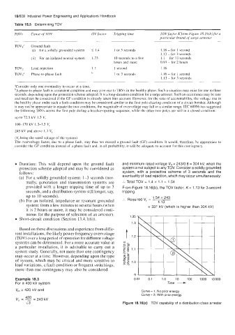
Example 18.3 0.01 0.1 1.0 Time - 1000 10000
100
10
For a 400 kV system
V, = 420 kV and Curve - 1, No prior energy.
Curve - 2, With prior energy.
420
V, = - 243 kV
=
45 Figure 18.16(a) TOV capability of a distribution class arrester