
Page 644 - Industrial Power Engineering and Applications Handbook
P. 644
Surge arresters: application and selection 18/609
”., ,
0.1
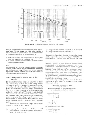
Figure 18.16(b) Typical TOV capability of a station class arrester
From the reproduced protective characteristics of this arrester, Zz = surge impedance of the equipment to be protected
as in Table 18.11, the nearest next higher rating available is Z, = surge impedance of the arrester at C’[
336 kV for a 420 kV system voltage. This is the basic rating
of the arrester which must be further checked for
Then applying Thevenin’sY’ theorem, the equivalent circuit
can be represented as shown in Figure 18.18(b). On
Whether its protective level can protect the BIL of the system
and/or the equipment it is protecting, and application of a voltage surge. the arrester will start
its energy capability to clear safely the long-duration
prospective voltage surges.
2’Thevenin’s theorem: This is one of the many theorem5 deduced
mathematically to solve intricate circuit. This theorem has
Note
Increasing the TOV level, i.e. choosing a higher protective established that it is possible to replace any network with linear
level (V,,,) of the arrester, may increase the life of the arrester parameters and comtant phasor voltage source\. a5 vieu cd from
but will reduce the margin of protection for the protected terminals, a and h. Figure 18.19(a). by a \ingle phasor voltage
source E with a single series impedance Z. Figure 18.19rb). The
equipment. Selection therefore should be done judiciously voltage E is the same that would appear across the terminals (I and
bearing all these aspects in mind.
h of the original network when these terminal\ are open circuited.
and the impedance Z. is that viewed from the same terminals when
18.6.2 Selecting the protective level of the all voltage sources within the network arc short-circuited. Thi\ can
arrester he illustrated by the following example.
Consider the simple switching circuit of Figure 18.191~). If we
For prospective voltage surges, as described in Table wish to find the current through the impedance Z3. on thc closure
18.1. which may arise in the system during normal of the snjitch, 5, then:
operation the protective characteristics of the surge arrester Voltaee across thij circuit (Zq ) before
I
a must be well below the BIL of the equipment at all closing the switch. ,E
points. For a minimum protective margin refer to Table I= Eauivalent imnedance. 2. of the remaiiiinz circuit
18.2. It is the basic parameter of a surge arrester that as seen from this \witch (Figure 18.19d)
defines its protective level. This is the voltage that will
appear across the arrester terminals and thus also across - E I
the equipment being protected during a current discharge
on the occurrence of a voltage surge. It should be well
below the BIL of the equipment under protection. Refer
to the load diagram shown in Figure 18.17. for more - E
clarity. z, z, ‘Z2
+
To determine this. consider the simple power circuit ~ %, +z,
diagram of Figure 18.18(a). where
and the voltage across this circuit
Z, = surge impedance of the line on which is connected
the equipment to be protected from the source of
supply up to the arrester