Page 639 - Industrial Power Engineering and Applications Handbook
P. 639
18/604 Industrial Power Engineering and Applications Handbook

            Considerations                             Parameters
                                                                  -
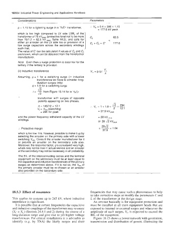
            p = 1 .I5 for a lightning surge in a KID transformer,   :.  V,,  = 0.4 x 386 x 1.15
                                                           = 177.6 kV peak
            which  is  too  high  compared  to  LV  side  LlWL of  the
            transformer of 75 kVPeak (protective level not to be more   CP   62.5
            than  75/1.2  =  62.5  kV peak, Table  18.2), and  calls  for   <
            either an arrester on the LV  side too  or  provision of  a   c, + c,  + c   177.6
            few  surge  capacitors  across  the  secondary  windings
            such that,
            The value of C' can be calculated if values of C, and C,
            are known, which can be obtained from the transformer
            manufacturer.
            Note  Even then a surge protection is essential for the
            tertiary if the tertiary is provided.
                                                               v,
            (ii) Inductive transference                V,, = p.9.r. -
                                                                n
            Assuming,  p= 1  for  a  switching surge  (in  inductive
                       transference we have to consider long-
                       duration surges only)
                    9=  1.8 for a switching surge
                         7
                        43
                     r= - from Figure 18.14 for a 'f&
                        fi
                        transformer  with  surges  of  opposite
                        polarity appearing on two phases.
                        n = 145/12 = 12.1              :_           &  294
                                                         v,, = 1 x  1.8 x - -
                                                                       x
                        V,  =  V,,,  (switching)                     2   12.1
                         = 294 kV peak                      = 37.9 kVpeak
            and the power frequency withstand capacity of the LV   = 28 kV,  s.
            windings                                        or  28 fi
                                                                   kV,,,,
            :.  Protective margin                           - 28fi  - 1.04
                                                              37.9
            which is too low. It is, however, possible to make it up by
            selecting the arrester on the primary side with a lower
            switching  V,,,.  Consult the arrester manufacturer for it
            or  provide  an  arrester  on  the  secondary  side  also.
            Moreover, the response factor, q is considered very high,
            which may not be true in actual service and an arrester
            at the secondary may not be necessary in all probability.
            The BIL of the interconnecting cables and the terminal
            equipment on the secondary must be at  least equal to
            the capacitive and inductive transferences of the primary
            surges as determined above. If it is not so, the  V,,,  of
            the primary arrester must be re-chosen or an arrester
            also provided on the secondary side.


         18.5.3 Effect of resonance                    frequencies that may cause such a phenomenon to help
                                                       to take corrective steps or modify the parameters C and
        This applies to systems up to 245 kV, where inductive   L of the transformer at the design stage.
         impedance is significant.                       An arrester basically is for equipment protection and
          It is possible that at certain frequencies the capacitive   must be installed at all main  equipment heads  that are
         and inductive couplings of the transformer may resonate   exposed to internal or external surges and whenever the
         (X,  = X,)  (Section 24.4.1 and 2) during the course of a   amplitude of  such surges, V,, is expected to exceed the
        long-duration surge and give rise to yet higher voltage   BIL of the equipment.
        transferences. For critical installations it is advisable to   Figure 18.15 shows a power network with generation,
        identify  (e.g.  by  TNA)  the  likely  surges  and  their   transmission  and distribution of  power, illustrating  the

