
Page 634 - Industrial Power Engineering and Applications Handbook
P. 634
Surge arresters: application and selection 18/599
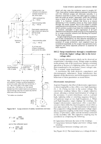
Cable junction, low which will also raise the incidence wave to roughly 2E.
/ refraction and reflection Then, there will be multiple reflections between the junctions
/ Arrester essential if V, > until the reflected surges will attenuate naturally. It is
/’ BIL of the cable therefore essential to protect the cable against surges at
33kV overhead line. both the ends as shown, particularly when the travelling
wave is likely to be of a higher value than the BIL of the
cable. It is, however, noticed that there is a natural
Interconnecting cable dampening of the travelling waves as they travel ahead
I-/ ( z sr- -loon) through the power system due to the system’s lumped
/I capacitances and inductances. Even the multiple reflections
I tend to achieve a peak of just twice the incidence surge. It
j
kz Electrostatic capacitances is, however, advisable to take cognisance of all such
,’help to tame and damp the reflections and refractions while carrying out the engineering
arriving surge for a surge protection scheme and deciding the location
r-‘ (VI = VreJ for the surge arresters.
&G Surges originating at some distance from the equipment
are of less consequence, for they become dampened as
Switching Interconnecting cable they propagate due to circuit parameters L and C. For the
device / (ZS2= loon) purpose of surge protection, each segment must be
considered separately as the surges may generate at any
segment and hence separate protection is essential for
each segment.
18.5.2 Surge transference through a transformer
(from the higher voltage side to the lower
,\ voltage side)
* *
This is another phenomenon which can be observed on
a transformer’s secondary circuit. Voltage surges occumng
‘ \) on the primary side of the transformer, during a switching
1
V,. (V,,, + 2.S.T - ynsformer operation or because of a lightning strike, have a part of
natural damping) (33111 kV) them transferred to the secondary (lower voltage) side.
zg
< BIL of cable z,, 2000 (1 $8 E This is termed ‘surge transference’.
m
=
A transformer has both dielectric capacitances and
electromagnetic inductances. Surge transference thus
depends on the electrostatic and electromagnetic transient
behaviour of these parameters as noted below.
Note Cable junction ‘b’ has a high refraction , *p
and reflection. Arrester would be essential to Relay Electrostatic transference
protect the cable rather than the transformer, if
2V,. > BIL of the cable. If the cable is long At power frequency, the effect of electrostatic capacitances
enough say, > 50 metre or so, the natural is almost negligible as they offer a very high impedance
dampening of the incident wave up to junction b, (X, 0~ 1o;f being too low) to the system voltage. The
may be enough and may not cause any harmful transformer windings behave like a simple inductive
effect even without the arrester circuit, allowing a normal transformation of voltage to
* All cables are sheathed the secondary. A system disturbance, such as a ground
fault, lightning strike or switching sequence, however,
will generate surges at very high frequencies,f,. When
such high-frequency surges impinge the windings, the
lumped (electrostatic) capacitances offer a near-short-
circuit to them while the electromagnetic circuit offers a
near-open circuit (X, -f,). The transformer now behaves
Figure 18.11 Surge protection of cables, transformer and motor like a capacitive voltage divider and causes voltage surges
due to capacitive coupling, in the lower voltage windings,
tertiary (if provided), cables and the terminal connected
on the secondary side. The capacitive coupling may be
E”= 2E- 4000 considered as comprising the following.
60 + 4000
2E Capacitance between the turns of the windings
0 Capacitance between higher and lower voltage main
and of the reflected wave windings
E, = E, 4000 - 60 Capacitance between windings and core.
60 + 4000
=E See Figure 18.12. The transformer as a voltage divider is