
Page 633 - Industrial Power Engineering and Applications Handbook
P. 633
18/598 Industrial Power Engineering and Applications Handbook
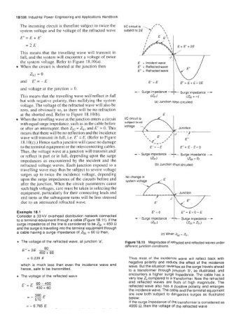
The incoming circuit is therefore subject to twice the I/C circuit is /--\
system voltage and the voltage of the refracted wave subject to 2 E y ‘1
E” = E + E’
=2E
This means that the travelling wave will transmit in
full, and the system will encounter a voltage of twice
the system voltage. Refer to Figure 18.10(a). E = Incident wave
When the circuit is shorted at the junction then E‘ = Reflected wave
E” = Refracted wave
zs2 = 0
and E’ = - E E‘ = E E“= E+ E=2E
and voltage at the junction = 0. Surge impedance -
- Surge impedance
This means that the travelling wave will reflect in full (ZSl) (ZSZ = 4
but with negative polarity, thus nullifying the system (a) Junction open circuited.
voltage. The voltage of the refracted wave will also be
zero, and obviously so, as there will be no refraction
at the shorted end. Refer to Figure 18.10(b).
When the travelling wave at the junction enters a circuit I/C circuit is
with equal surge impedance, such as in the cable before
or after an interrupter, then Z,, = Zs, and E‘ = 0. This voltage Junction
means that there will be no reflection and the incidence
wave will transmit in full, Le. E’ =E. (Refer to Figure
18.10(c).) Hence such a junction will cause no damage
to the terminal equipment or the interconnecting cables. E”=E-E=O
Thus, the voltage wave at a junction will transmit and/ Surge impedance -
or reflect in part or in full, depending upon the surge - Surge impedance
impedances as encountered by the incident and the (ZSZ = 0)
refracted voltage waves. Each junction exposed to a (b) Junction short circuited
travelling wave may thus be subject to severe voltage
surges up to twice the incidence voltage, depending
No change in
upon the surge impedances of the circuits before and system voltage
after the junction. When the circuit parameters cause
such high voltages, care must be taken in selecting the
equipment, particularly for their connecting leads and Junction
end turns as the subsequent turns will be less stressed
due to an attenuated refracted wave.
Example 18.1 E‘=O Surge impedance -
Consider a 33 kV overhead distribution network connected - Surge impedance
to a terminal equipment through a cable (Figure 18.11). If the
surge impedance of the line is considered to be Z,, = 450 R (ZSZ = Zsd
and the surge is travelling into the terminal equipment through
a cable having a surge impedance of Z,, = 60 R then, (c) When Z,, = Zsl
The voltage of the refracted wave, at junction ‘a’, Figure 18.10 Magnitudes of refracted and reflected waves under
different junction conditions.
E” = 2E. ~ 60
450 + 60
= 0.235 E Thus most of the incidence wave will reflect back with
negative polarity and reduce the effect of the incidence
which is much less than even the incidence wave and wave. But the situation reverses as the surge travels ahead
hence, safe to be transmitted.
to a transformer through junction ‘b’, as illustrated, and
encounters a higher surge impedance. The cable has a
The voltage of the reflected wave
very low Z, compared to a transformer. Now the refracted
and reflected waves are both of high magnitude. The
E‘= E. ~ 60 - 450
450 + 60 reflected wave also has a positive polarity and enlarges
the incidence wave. The cable and the terminal equipment
390 E
=-_ are now both subject to dangerous surges as illustrated
51 0 below:
If the surge impedance of the transformer is considered as
= - 0.765 E 4000 0, then the voltage of the refracted wave