
Page 630 - Industrial Power Engineering and Applications Handbook
P. 630
Surge arresters: application and selection 18/595
Table 18.2 Recommended protection margins
Voltage v,,, Recommended mat qui\
-Voltage impulsc range ~~~~
KV For swtrthrng For lightning For
surges \urge\ FOWy
~~ ~ ~~ ~
I Decided by the
Table 13.2 2 3.6-245 lightning wrge. I 05 I IS
which 15 more
Eevere
I1
Table 13.3
18.4.3 Margin for contingencies
Rise time for Is - tl(/s) 4
Rise lime for V,- tl(~,) An additional protection margin may be considered for
the contingencies noted below, depending upon the
Rise bme (ps) --t
(
r, (1s) ’ VI) criticality of a system or its susceptibility to overvoltages.
ti
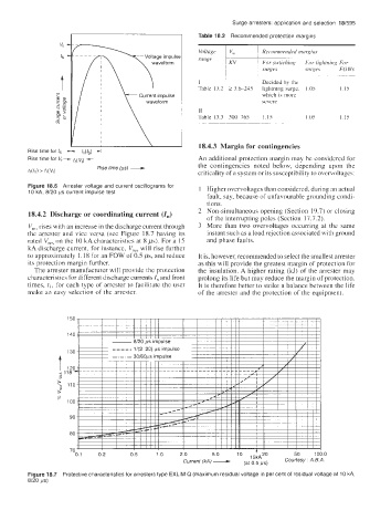
Figure 18.6 Arrester voltage and current oscillograms for 1 Higher overvoltages than considered. during an actual
10 kA, 8/20 ps current impulse test
fault, say, because of unfavourable grounding condi-
tions.
18.4.2 Discharge or coordinating current (I,) 2 Non-simultaneous opening (Section 19.7) or closing
of the interrupting poles (Section 17.7.2).
V,,, rises with an increase in the discharge current through 3 More than two overvoltages occurring at the same
the arrester and vice versa (see Figure 18.7 having its instant such as a load rejection associated with ground
rated V,,, on the 10 kA characteristics at 8 ps). For a 15 and phase faults.
kA discharge current, for instance, V,, will rise further
to approximately 1.18 for an FOW of 0.5 ,us, and reduce It is, however, recommended to select the smallest arrester
its protection margin further. as this will provide the greatest margin of protection for
The arrester manufacturer will provide the protection the insulation. A higher rating (kJ) of the arrester may
characteristics for different discharge currents I, and front prolong its life but may reduce the margin of protection.
times, t,, for each type of arrester to facilitate the user It is therefore better to strike a balance between the life
make an easy selection of the arrester. of the arrester and the protection of the equipment.
50
40
- - - - - 1/(2-20) ps impulse
30
t -.-.- 30160~s impulse
0
Current (kA) A ps) Courtesy A B A
Figure 18.7 Protective characteristics for arresters type EXLIM Q (maximum residual voltage in per cent of residual voltage at 10 kA,
8/20 ps)