
Page 632 - Industrial Power Engineering and Applications Handbook
P. 632
Surge arresters: application and selection 181597
which such levels can be quickly established, except E-.
experience. The project engineer is the best judge of the
most appropriate level of BIL, depending upon the surge I Junction (E + E’)
protection scheme. Below we briefly discuss the effect
of surge reflections and transferences on the safety of
equipment to arrive at the right choice of BIL and the
surge protection criteria.
18.5.1 Reflection of the travelling waves
The behaviour of’ a transient wave at a junction of two
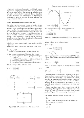
conductors, such as at junction Jin Figure 18.8, is similar Surge impedance -
to that of water, when it passes through one large-diameter -Surge impedance
pipe to another of a smaller diameter. Some of the water VSl) (ZSi
will flow ahead and the remainder will backflow at the E = Incident wave
junction. Similarly, a transient wave will also reflect in E’ = Reflected wave
part or in full at a junction between two conductors of E” = Refracted wave
different surge impedances, depending upon the surge
impedance of the circuit ahead of the junction. This would Figure 18.9 Illustration of the reflection of a TRV at a junction
give rise to two types of waves, i.e.
and the voltage of the refracted wave
Refracted wave: a wave that is transmitted beyond the
junction. E” = E + E‘
0 Reflected wave: a wave that is repelled at the joint. )
=E+E-( z,, - z,,
See Figure 18.9 zsz + zsi
To analyse this phenomenon refer to Figure 18.8,
(I 8.4)
If Z,, = surge impedance of the incoming circuit
Z,, = surge impedance of the outgoing circuit (Figure If the outgoing circuit is inductive (Figure 18.8(b)) as in
18.8(a)) a motor, transformer or an inductor coil, with an inductance
E = voltage of the incident wave (incoming wave) L then
E’ = voltage of the reflected wave.
E” = voltage of the refracted (transmitted) wave. (1 8.5)
then the voltage of the reflected wave
and if it is capacitive (Figure 18.8(c)) with a capacitance
E’ = E, zs2 - zsi (I 8.3) C then
ZS? + zsi
( 18.6)
This can also be derived for a combined R, L and C
Junction circuit to obtain more accurate data. Generally. the figure
Y-7 obtained through equation (18.4) is simpler, quicker and
provides almost correct information for the purpose of
surge analysis, and is used more in practice. Where,
however, more accurate data are necessary, such as for
academic interest, then the morc rclcvant formulac may
be used.
E 3
Surge impedance thus plays a significant role in
(a) determining the magnitude of the reflected wave that
matters so much in adding to thc TRVc. (Also refer to
graphs of Figure 17.7 corroborating this analysis.)
When the circuit is open at the junction then
zs2 =
E‘ = E, Le. the travelling wave will reflect in full.
The voltage at the junction
=E+E‘
Figure 18.8 Different parameters of switching circuits =2E