Page 629 - Industrial Power Engineering and Applications Handbook
P. 629
18/594 Industrial Power Engineering and Applications Handbook
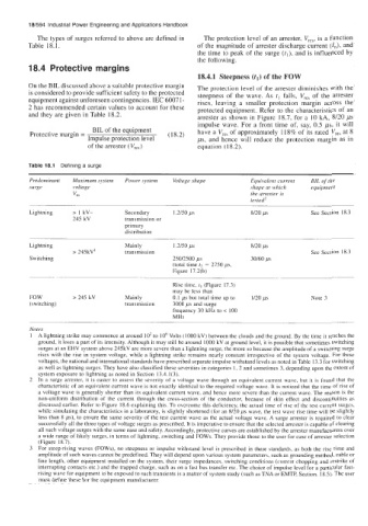
           The types of  surges referred to above are defined in   The protection level of an arrester, V,,,,  is a function
         Table 18. I.                                  of the magnitude of arrester discharge current (I,),  and
                                                       the time to peak of the surge (tl), and is influenced by
                                                       the following.
         18.4  Protective margins
                                                       18.4.1  Steepness (tl) of the FOW
         On the BIL discussed above a suitable protective margin   The protection level of the arrester diminishes with the
         is considered to provide sufficient safety to the protected   steepness  of  the  wave. As  tl falls,  V,,,  of  the  arrester
         equipment against unforeseen contingencies. IEC 6007 1 -   rises,  leaving  a  smaller  protection  margin  across  the
         2 has recommended certain values to account for these   protected equipment. Refer to the characteristics of  an
         and they are given in Table 18.2.             arrester as shown in Figure  18.7, for a  10 kA, 8/20 ps
                                                       impulse  wave. For a front  time  of,  say, 0.5 ps, it will
                          BIL of the equipment         have a V,,,  of approximately  118% of its rated V,,,  at 8
         Protective margin =                   (1 8.2)
                         Impulse protection  level     ps, and hence  will  reduce the  protection  margin  as in
                         of the arrester ( VreS)       equation  (1 8.2).

         Table 18.1  Defining a surge
         Predominant   Maximum system   Power system   Voltage shape   Equivalent current   BIL of the
         surge       voltage                                          shape at which   equipment
                     vm                                               the arrester is
                                                                      tested'
         Lightning   > I  kV-      Secondary    1.2/50 ps             8/20 ps         See Section  18.3
                     245 kV        transmission  or
                                   primary
                                   distribution

         Lightning                 Mainly       1.2/50 p5             8/20 ps
                     > 245kV'      transmission                                       See Section  18.3
         Switching                              250/2500 ps           30/60 ps
                                                (total time t2 = 2750 ps,
                                                Figure  17.2(b)
         ~-                            .- ._~                                ~.
                                                Rise time, t, (Figure 17.3)
                                                may be less than
         FOW         > 245 kV      Mainly       0.1 ps but total time up to   1/20 ps   Note 3
         (switching)               transmission   3000 ps  and surge
                                                frequency  30 kHz to < 100
                                                MHz
         Notes
           A lightning strike may commence at around  IO2 to  10'  Volts (1000 kV) between the clouds and the ground. By the time it reaches the
           ground, it loses a part of its intensity. Although it may still be around  1000 kV at ground level, it is possible that sometimes switching
           surges at an EHV system above 245kV are more severe than a lightning surge, the more so because the amplitude of a switching surge
           rises  with  the rise  in system  voltage,  while  a lightning strike remains  nearly  constant irrespective  of  the  system  voltage.  For these
           voltages, the national and international standards have prescribed separate impulse withstand levels as noted in Table 13.3 for switching
           as well as lightning surges. They have also classified these severities in categories I, 2 and sometimes 3, depending upon the extent of
           system exposure to lightning as noted in Section 13.4.1(3).
           In  a surge arrester, it is easier to assess the severity  of  a voltage  wave  through  an  equivalent current  wave, but  it is found  that the
           characteristic of an equivalent current wave is not exactly identical to the required  voltage wave. It is noticed that the time of rise of
           a voltage wave is generally  shorter than its equivalent current wave, and hence more severe than the current wave. The reason is the
           non-uniform distribution  of  the  current  through  the  cross-section  of  the  conductor, because  of  skin  effect  and  discontinuities  as
           discussed earlier. Refer to Figure  18.6 explaining this. To ovcrcomc this deficiency, the actual time of rise of the test current  surges,
           while simulating the characteristics in a laboratory, is slightly shortened  (for an  8/20 ps  wave, the test wave rise time will be slightly
           less than  8 ps), to ensure the same severity of the test current  wave as the actual voltage  wave. A surge arrester is required  to clear
           successfully all the three types of voltage surges as prescribed. It is imperative to ensure that the selected arrester is capable of clearing
           all such voltage surges with the same ease and safety. Accordingly, protective curves are established by the arrester manufacturers over
           a wide range of likely surges, in terms of lightning, switching and FOWs. They provide those to the user for ease of arrester selection
           (Figure 18.7).
           For steep-rising waves  (FOWs), no steepness or impulse  withstand  level is prescribed  in  these  standards, as both  the rise  time  and
           amplitude of such waves cannot be predefined. They will depend upon various system parameters,  such as grounding method, cable or
           line length, other equipment installed  on the system, their surge impedances,  switching conditions (current chopping and restrike  of
           interrupting contacts etc.) and the trapped charge, such as on a fast bus transfer etc. The choice of impulse level for a particular  fast-
           rising wave for equipment to'be exposed to such transients is a matter of system study (such as TNA or EMTP, Section. 18.5). The user
           must define these for the equipment  manufacturer.

