Page 631 - Industrial Power Engineering and Applications Handbook
P. 631
18/596  Industrial Power Engineering and Applications Handbook
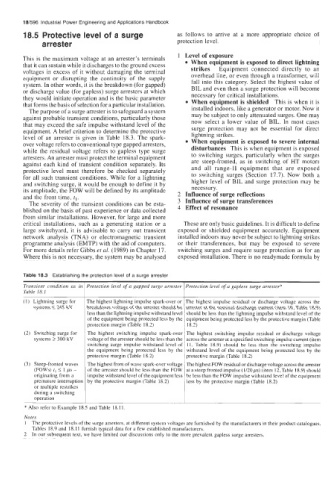
        18.5  Protective level of a surge              as  follows  to  arrive  at  a  more  appropriate  choice  of
              arrester                                protection level.
                                                       1  Level of exposure
        This is the maximum voltage at an arrester’s terminals   When equipment is exposed to direct lightning
        that it can sustain while it discharges to the ground excess   strikes
                                                                   Equipment  connected  directly  to  an
        voltages in excess of it without damaging the terminal   overhead line, or even through a transformer, will
        equipment  or disrupting  the  continuity  of  the  supply   fall into this category.  Select the highest value of
        system. In other words, it is the breakdown (for gapped)   BIL and even then a surge protection will become
        or discharge value (for gapless) surge arresters at which   necessary for critical installations.
        they would initiate operation and is the basic parameter   When equipment is shielded  This is when it is
        that forms the basis of selection for a particular installation.
          The purpose of a surge arrester is to safeguard a system   installed indoors, like a generator or motor. Now it
        against probable transient conditions, particularly those   may be subject to only attenuated surges. One may
                                                           now  select  a  lower  value  of  BIL.  In  most  cases
        that may exceed the safe impulse withstand level of the
        equipment. A brief  criterion to determine the protective   surge  protection  may  not  be  essential  for  direct
        level  of  an arrester is given in Table  18.3. The spark-   lightning strikes.
        over voltage refers to conventional type gapped arresters,   When equipment is exposed to severe internal
        while the residual voltage refers  to gapless type  surge   disturbances  This is when equipment is exposed
        arresters. An arrester must protect the terminal equipment   to switching surges, particularly when the surges
        against each kind  of  transient  condition  separately. Its   are  steep-fronted,  as  in  switching  of  HT motors
        protective  level  must  therefore  be  checked  separately   and  all  range-I1 equipment  that  are  exposed
        for all such transient  conditions. While for a  lightning   to  switching  surges  (Section  17.7). Now  both  a
        and switching surge, it would be enough to define it by   higher  level  of  BIL and surge protection  may be
                                                           necessary.
        its amplitude, the FOW will be defined by its amplitude   2  Influence of surge reflections
        and the front time, t,.                        3  Influence of surge transferences
          The severity of  the transient conditions can be esta-
        blished on the basis of past experience or data collected   4  Effect of resonance
        from similar installations. However, for large and more
        critical  installations,  such  as a generating station or a   These are only basic guidelines. It is difficult to define
        large switchyard,  it  is advisable to  carry  out  transient   exposed  or shielded  equipment  accurately. Equipment
        network  analysis  (TNA) or  electromagnetic  transient   installed indoors may never be subject to lightning strikes
        programme analysis (EMTP) with the aid of computers.   or  their  transferences,  but  may  be  exposed  to  severe
        For more details refer Gibbs et al. (1989) in Chapter 17.   switching surges and require surge protection as for an
        Where this is not necessary, the system may be analysed   exposed installation. There is no readymade formula by

        Table 18.3  Establishing the protection level of a surge arrester
        Transient  condition  as  in  Protection  level of  a gapped  surge arrester  Protection level of  a gapless surge arrester*
        Table 18.1
        (I)  Lightning surge for   The highest lightning impulse spark-over or  The highest  impulse  residual  or  discharge  voltage  across  the
           systems I245 kV   breakdown  voltage of the arrester should be  arrester at the nominal discharge current (item  10, Table 18.9)
                           less than the lightning impulse withstand level  should be less than the lightning impulse withstand level of the
                           of the equipment being protected less by the  equipment being protected less by the protective margin (Table
                           protection  margin (Table 18.2)   18.2)
        (2)  Switching surge for   The  highest  switching  impulse  spark-over  The highest  switching  impulse  residual  or  discharge  voltage
           systems 2 300 kV   voltage of the arrester should be less than the  across the arrester at a specified switching impulse current (item
                           switching  surge impulse  withstand  level  of  11, Table  18.9)  should  be  less  than  the  switching  impulse
                           the  equipment being  protected  less  by  the  withstand  level  of  the equipment being protected  less by  the
                           protective  margin (Table 18.2)   protective  margin (Table 18.2)
        (3)  Steep-fronted  waves   The highest front of wave spark-over voltage  The highest FOW residual or discharge voltage across the arrester
           (FOWs) tl 5 1 ps  -   of thc arrcstcr should be less than the FOW  at a steep fronted impulse (1/20 ps) (item 12, Table 18.9) should
           originating from a   impulse withstand level of the equipment less  be less than the FOW impulse withstand level of the equipment
           premature interruption  by  the protective  margin (Table  18.2)   less by  the protective  margin (Table  18.2)
           or multiple restrikes
           during a switching
           operation
        * Also refer to Example 18.5 and Table  18.1 1
        Notes
        1  The protective levels of the surge arresters, at different system voltages are Curnished by the manufacturers in their product catalogues,
          Tables  18.9 and 18.11 furnish typical data for a few established manufacturers.
        2  In our subsequent text, we have limited our discussions only to the more prevalent  gapless surge arresters.

