
Page 635 - Industrial Power Engineering and Applications Handbook
P. 635
18/600 Industrial Power Engineering and Applications Handbook
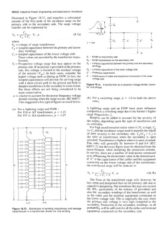
illustrated in Figure 18.13, and transfers a substantial
amount of the first peak of the incidence surge on the
primary side to the secondary side. The surge voltage
transfer can be expressed by
c
v -A. (8.7a)
IC - c, + c, VI .P
where f, = Ips
V,, = voltage of surge transference
Cp = lumped capacitance between the primary and secon- - 1 1
dary windings I,
C, = lumped capacitance of the lower voltage side.
These values are provided by the transformer manu- V, - Surge on the primary side
facturer. fit, - Surge transference on the secondary side
V, = Prospective voltage surge that may appear on the C, - Lumped capacitance between the primary and the secondary
primary side. If an arrester is provided on the primary windings
side, this voltage is limited to the residual voltage C, - Lumped capacitance of the lower voltage side
of the arrester (Vre5). In both cases, consider the C’ - Protective capacitance
higher voltage such as during an FOW. In fact, the C - Capacitance of cable and equipment connected on the lower
lumped capacitances will provide the arriving surge voltage side
with a short-circuit path to the ground and help to
Figure 18.1 3 A transformer as a capacitor voltage divider, drawn
dampen transference to the secondary to some extent. for one phase
But these effects are not being considered to be
more conservative.
p = a factor to account for the power frequency voltage
already existing when the surge occurs. IEC 6007 1 - (b) For a switching surge, p = 1.0 in both the above
2 has suggested a few typical figures as noted below: cases.
(a) For a lightning surge and FOW : A lightning surge and an FOW have more influence
For Y/A or A/Y transformers, p = 1.15 compared to a switching surge due to the former’s higher
For Y/Y or &A transformers, p = 1.07 surge frequencies, f,.
Margins can be added to account for the severity of
the surges, depending upon the type of installation and
its criticality.
For high transformation ratios when V,lV2 is high, Cp
>> C, and the incidence surges tend to transfer the whole
of their severity to the secondary side. Cp/(Cp + C,) is
the ratio of transference when the secondary is open
circuited. Transference is highest when it is open circuited.
This ratio will generally lie between 0 and 0.4 (IEC
60071-2), but the exact figure must be obtained from the
manu-facturer, when designing the protection scheme.
In service, there are a number of load points connected
to it, influencing the electrostatic value in the denominator.
If ‘C‘ is the capacitance of the cables and the equipment
connected on the lower voltage side of the transformer,
the transferred surge will be reduced to
v- CP vt .P (18.7b)
IC - c, + c, + c
The front of the transferred surge will, however, be
less steep and dampened than on the primary side due to
capacitive dampening. But sometimes this may also exceed
the BIL, particularly of the tertiary (if provided) and
also the secondary windings of the transformer, as well
as the cable and the terminal equipment connected on
the lower voltage side. This is especially the case when
L.V. H.V. the primary side voltage is very high compared to the
secondary. Protection of the secondary windings, in all
Figure 18.12 Distribution of winding inductances and leakage probability, will be sufficient for all the cables and terminal
capacitances in a transformer shown for one winding equipment connected on the secondary side.