
Page 638 - Industrial Power Engineering and Applications Handbook
P. 638
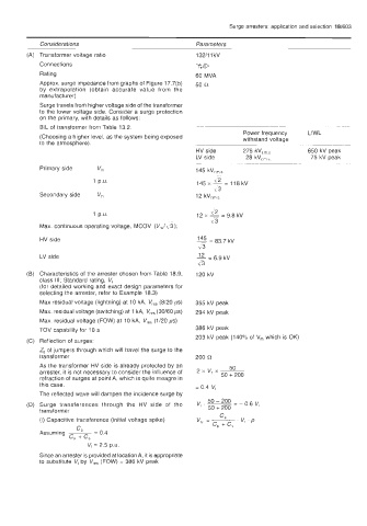
Surge arresters: application and selection  18/603

            Considerations                             Parameters
            Transformer voltage  ratio                 132/11 kV
            Connections                                %ID
            Rating                                     60 MVA
            Approx. surge impedance from graphs of Figure 17.7(b)   50 0
            by  extrapolation  (obtain  accurate  value  from  the
            manufacturer)
            Surge travels from higher voltage side of the transformer
            to the  lower voltage  side.  Consider a surge  protection
            on the  primary, with details as follows:
            BIL of transformer  from Table 13.2.
                                                                    Power frequency   LlWL
            (Choosing a higher level, as the system being exposed   withstand voltage
            to the atmosphere).                                                        ~~~
                                                                           ,
                                                       HV side      275 kVr ,         650 kV peak
                                                       LV side       28 kvrms          75 kV peak
                                                                     ~~~          ~~
            Primary side    vm                         145 kV,,,
                           1 p.u.                      145 x   lr2   = 118 kV
                                                            lr3
            Secondary side   V,                        12kVrrms

                                                           \' 2
                           1 p.u                       12 x  - = 9.8 kV
                                                           1' 3
            Max. continuous operating voltage,  MCOV  (Vm/% 3);
            HV side                                    145 = 83.7 kV
                                                        v3
            LV side                                    12 = 6.9 kV
                                                        -\I 3
            Characteristics of the arrester chosen from Table 18.9,   120 kV
            class  111;  Standard rating,  V,
            (for detailed working and exact  design parameters for
            selecting the arrester,  refer to Example 18.3)
            Max residual voltage (lightning) at 10 kA, V,,,  (8/20 ps)   355 kV peak
            Max. residual voltage (switching) at 1 kA, V,,,  (30/60 ps)   294 kV peak
            Max. residual voltage  (FOW) at 10 kA, Vr,,   (1/20 ps)
            TOV capability for  10 s                   386 kV peak
                                                       203 kV peak (140% of V,   which is OK)
            Reflection of  surges:
            Z, of jumpers through which will travel the surge to the
            transformer                                200 R
            As the transformer  HV side is already  protected by an   2XV1X-   50
            arrester, it is not necessary to consider the influence of   50 + 200
            refraction of surges at point A, which is quite meagre in
            this case,                                 = 0.4 V,
            The reflected wave will dampen the incidence surge by
                                                          50 - 200
            Surge  transferences  through  the  HV  side  of  the   V,  . ~  50 + 200   = - 0.6 V,
            transformer
            (i) Capacitive transference (initial voltage  spike)
                      C
            Assuming       = 0.4
                    c, + cs
                         V,  = 2.5 P.U.
            Since an arrester is provided at location A, it is appropriate
            to substitute  V,  by  V,,,  (FOW) = 386 kV peak