Page 640 - Industrial Power Engineering and Applications Handbook
P. 640
Surge arresters. application and selection  18/605
         influences of the different kinds of surges that may appear   18.6.1 TOV capability and selection of
         in  the  system  and  which  must  be  taken  into  account,   rated voltage, V,
         while engineering a surge protection scheme for such a
         system or a part of  it.                       TOV  is  considered  only  to  select  the  MCOV  and  the
                                                        rated voltage, V,, of the surge arrester. This is a reference
                                                        parameter  to define  the operating  characteristics of  an
          18.6  Selection of a gapless surge            arrester.  It plays no part  in deciding the protective level
               arrester                                 of the arrester, which is solely dependent on the transient
                                                        conditions of the system, as discussed later. V,. is used to
                                                        make  the  right  choice  of  an  arrester  and  its  energy
         To  provide  the  required  level  of  surge  protection  for   absorption capability to ensure that it does not fail under
         equipment or a power system against possible transient   the system's prospective transient conditions.
         frequency  voltage  surges, ZnO gapless  surge arresters   To determine the level of TOVs and their duration, it
         are the latest in the field of insulation coordination. We   is essential to analyse all the possible TOVs the system
         pro\;ide below a procedure to select the most appropriate   may  generate during actual operation, and then  decide
         type  and sizc of  a ZnO surge arrester  for the required   on  the  mosl  crucial  of them.  as  shown  in  Table  18.5.
         insulation coordination. Based on the discussions above,   Surge arrester manufacturers provide their TOV capability
         the f'ollowing will form the basic parameters to arrive at   curves in the shape of TOV strength versus duration of
         the  most  appropriate choice:                 the TOV. Afew typical TOV capability curves are shown
                                                        in  Figure  18.16(a)  for  distribution  class  and  Figure
            Service conditions: As for other equipment (e.g. motors,   18.16(b) for station class surge arresters. They indicate
            transformers  or  switchgears)  a  surge  arrester  is   the  ratio  between  V, and  Vr  which  may  vary  from
            influenced too by  unfavourable operating conditions   manufacturer  to  manufacturer  and  is  termed  the TOV
            such as noted in Table  18.4.               strength factor K. For curve  18.16(b) i1 is typically
              Unfavourable  operating  conditions  will  require  a
            derating  in  the  rating of  a  surge arrester or special   v, = 0.8 v,
            surface treatment and better clearances. Refer to the   Generalizing  this  for different  condition4  of  TOV  and
            manufacturer for the required measures and/or deratings.
            Mechanical soundness: Such as strength to carry the   make of  surge arrester,
            weight of conductor and the stresses so caused, pressure   V, = K  ' V,
            of wind and, in extremely cold climates, the weight
            of  ice.                                    For each kind of TOV and its duration, a corresponding
            Maximum continuous operating voltage (MCOV) V,:   factor (K) is  obtained  and  with  this  is  determined  the
            This  voltage  is  selected  so that  the  highest  system   required rating, V,. of the arrester. The most crucial TOV
            voltage,  VI,,,  as  in  column  2,  Tables  13.2  or  13.3,   may be selected as the rating of the arrester. If it is not a
            when  applied to the arrester is  less th?!   or equal to   standard  rating  as  in  the  manufacturer's  catalogue  as
            the arrester MCOV, that is,  V, 2 Vln/y'3.   shown in Tables 18.9 and 18.11, one may select the next
            The  BIL of  the equipment being protected  (Section   higher rating  available. A  simple procedure  is outlined
            18.3).                                      in Table  18.5 for a quick reference.
            'l'he  arrester's  nominal  discharge  current  (In): This
               ifies an arrester and is the peak value of a lightning
            current impulse wave (8/20 ps) that may pass through   To determine TOV
            the arrester for which it i5 designed. It may be one of   The main   cause^  of  TOV, a\ discu\\ed  above, may  be
            the following:
                                                        one or more of the following.
             1.5, 2.5, S,  IO and 20 kA
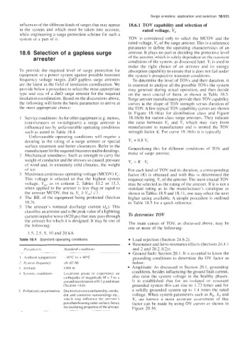
         Table 18.4  Standard operating conditions        Load rejection (Section 24.6.2).
                                                          Resonance and ferro-resonance effects (Sections 24.3.1
           Pirrcirnrrrr.\   Staridrird conditions         and 2 and 20.2.1(2)).
         . .-     ~~~~                                    Ground fault: Section 20. I. It is essential to know the
          I  Ambient temperature   -40°C  to + 40°C       grounding  conditions  to determine  the  OV factor as
         2  Sl stem frequency   48-62  HI                 below:
         3  Altitude         IO00 m                       Amplitude:  As  discussed  in  Section 20.1, grounding
         1 Seismic conditionc   Locations  prone  to  experience an   conditions, besides influencing the ground fault current,
                            earthquake of magnitude M  = 5  or a   also raise  the  system  voltage in  the  healthy  phases.
                            ground acceleration of 0.1 g and more   It  is  established  that  for  an  isolated  ur  resonant
                            (Section  14.6)               grounded  system this  can  rise  to  1.73 times  and  for
         5  Pollution/contamination   Due to excessive rain humidity, smoke,   a  solidly grounded  system up to  1.4 times the rated
                            dirt  and corrosive surroundings etc.,   voltage. When system parameters such as Ro, X,, and
                             wlricli  may  influence  the  arrester's   X,  are  known  a  more  accurate  assessment  of  this
                            porcelain housing outer burface, hence   factor can be  made by  using OV curves as shown in
                            the insulating properties ofthe arrester.   Figure  20.16.
                              ~~~~~~   ~~

