Page 645 - Industrial Power Engineering and Applications Handbook
P. 645

18/61 0  Industrial Power Engineering and Applications  Handbook
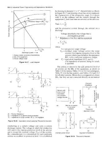
                                                       by drawing its elements' I  0~  V" characteristics as shown
                                                       in Figure 18.17 and drawing a load line on it to represent
                                                       the characteristic  of  the prospective  surge. It is  drawn
                                                       with  V, as  the  ordinate  and  the  current  through  the
                                                       equipment I, (had there been no arrester) as the abscissa:
                                                                VI
                                                       Then  I, = -
                                                                z,
                                                       and  the  protective  current  through  the  arrester  on  a
                                                       discharge
                                                            Voltage absorbed or the voltage that is
                                                                   discharged to ground
                                                       I,  =
                                                           Impedance of the line and the equipment


                      Discharge current -  7           where  V,,,  = residual  surge  voltage  across  the  surge
                        4
                                                             V, = prospective surge voltage
                                   /  - VI  - Vre,
                        /"
                                       -
                                    p
                                                                arrester) which must be below the equipment
             1. Surge arrester protective characteristics       arrester (the impulse protective level of the
             2. BIL of the equipment.                           BIL, with a sufficient protective margin,
             3. Actual voltage surge.                  and   Z, = equivalent impedance of Z, and Z2.
                                                                (the impedance of arrester, being too small,
                    Figure 18.17  Load diagram
                                                                is ignored)
                                                         The criteria to determine the safe protective level of
                                                       an  arrester are the BIL of  the equipment, as shown  in
                                                       Table 1 1.6 for motors, Tables 13.2 or 14.1 for switchgears,
                                                       Table 32.1(A) for bus systems, and Tables 13.2 and 13.3
                                                       for all other systems. Motors have a comparatively lower
                                                       BIL, but they are not connected directly on an outdoor

                                                                                    Constant
         i  qe7Thes                                                                 impedance   a
         r4
                                Z,
                             . .. r - ----L  ~.
                                                         Network with
                                    ,
                             ,
                               I ____.
                             :
                                   ~
                                  1
                                                         linear circuit
                                ZI
                                    I
                               r
                                                         parameters
                               --
                               ......
                                    I
                             ;-- ---L..
                                    I
                               I
                             ,
                                                         and constant
                                                         voltage sources
                                                                              m              x9
                                                                 May be connected
                                                                   to any other        (b)    b
           (b)
                                                                    network.        Thevenin's
                                                                                   equivalent circuit
                  -G                     TG
         Z, =  Source impedance
         Z, =  Impedance of  equipment being protected
         Z, =  Impedance of  surge arrester. At  V,,  it is negligible                   Z,
         Figure 18.18  Equivalent circuit applying Thevenin's theorem
         conducting  at  a  certain  voltage  and  carry  a  certain
         discharge current. The voltage at which the conduction
         will  start is the impulse protective level of  the arrester   (c)           (d)
         and is termed the residual voltage  (Vre5) of the arrester.   A simple power circuit   Equivalent impedance
         By  a  manufacturer it is determined for each particular
         arrester to establish its protective level. It is established   Figure 18.19  Thevenin's theorem
   640   641   642   643   644   645   646   647   648   649   650