
Page 654 - Industrial Power Engineering and Applications Handbook
P. 654
Surge arresters: application and selection 18/61 9
complex subject. However, there are a number of methods
to determine this. IEC 60095-5 mentions a few methods
by which the resistive leakage current, I,, can be measured
through IZnO. The main problem faced in all these Monitor
methods is the presence of a system voltage third harmonic
that finds its way through the grounded arrester and shows
up in IZnO. Therefore, unless the system voltage third Monitor
harmonic is eliminated from IZnO, it will not provide a ground wire
true replica of the arrester's condition. Below we discuss
one more recognized method (See Lundquist et al., 1989)
by which an attempt is made to separate out the system
voltage third harmonic from IZnO. The method is based
on extraction of I, by third-order harmonic analysis of
IZnO. This is achieved by providing an electric field
probe located at the grounding end of the arrester. The
probe compensates the third harmonic present in the
system voltage so that the current measured at the ground
end of the arrester contains only the third harmonic of I,.
Harmonics, other than the third even if they are present I 1
in the system or IZnO, are of little relevance, as the Current
instrument analyses only the third harmonic. Adapter probe with
cable
The instrument separates out I, and I, and provides a
direct reading of I, and hence the condition of the arrester. Figure 18.24(a) Leakage current monitor with accessories
(Courtesy: TransiNor As)
Refer to Table 18.10 providing a brief procedure to monitor Power line
the condition of an arrester through such a monitor.
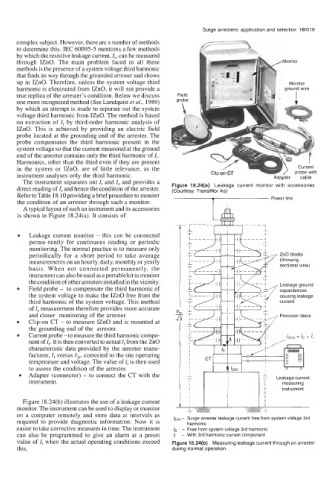
A typical layout of such an instrument and its accessories
is shown in Figure 18.24(a). It consists of
Leakage current monitor - this can be connected
perma-nently for continuous reading or periodic
monitoring. The normal practice is to measure only
periodically for a short period to take average ZnO blocks
measurements on an hourly, daily, monthly or yearly (Showing
basis. When not connected permanently, the sectional view)
instrument can also be used as a portable kit to monitor
the condition of other arresters installed in the vicinity.
Field probe - to compensate the third harmonic of Leakage ground
capacitances
the system voltage to make the IZnO free from the causing leakage
third harmonic of the system voltage. This method current
of I, measurement therefore provides more accurate "I I I"
and closer monitoring of the arrester. Porcelain discs
Clip-on CT - to measure IZnO and is mounted at
the grounding end of the arrester.
Current probe - to measure the third harmonic compo-
nent of I,. It is then converted to actual I, from the ZnO
characteristic data provided by the arrester manu-
facturer, I, versus 13,, corrected to the site operating
temperature and voltage. The value of I, is then used
to assess the condition of the arrester.
Adapter (connector) - to connect the CT with the
instrument.
instrument
Figure 18.24(b) illustrates the use of a leakage current
monitor. The instrument can be used to display or monitor
on a computer remotely and store data at intervals as -
required to provide diagnostic information. Now it is lzno Surge arrester leakage current free from system voltage 3rd
harmonic
easier to take corrective measures in time. The instrument lc - Free from system voltage 3rd harmonic
can also be programmed to give an alarm at a preset I, - With 3rd harmonic current component
value of I, when the actual operating conditions exceed Figure 18.24(b) Measuring leakage current through an arrester
this. during normal operation