
Page 667 - Industrial Power Engineering and Applications Handbook
P. 667
19/632 Industrial Power Engineering and Applications Handbook
choice of interrupting device may result in insulation
failure of the terminal equipment, such as a power -Tulip
transformer, an induction motor or interconnecting cables. .. contacts
This situation may arise when: Terminal
bushings
1 Interrupting small magnetizing currents, such as inter-
rupting an induction motor or a transformer on no-
load, a situation, when the current may lag the impressed
voltage by nearly 90".
2 Interrupting a charged capacitor bank, when the current
will lead the impressed voltage by nearly 90".
3 Interrupting an unloaded transmission or distribution
line or a cable, Le. interrupting a line charging current,
which is capacitive and may lead the system voltage
by nearly 90". Arc control
pots
4 Interrupting an induction motor immediately after a
switch on, when the current is large and highly induc- Moving
tive. contacts
5 Interrupting fault currents that are mostly inductive
(Section 13.4.1) and occur at very low power factors.
They are excessive in magnitude, and cause high
thermal effects and electromagnetic* forces on the Oil tank
arc chamber, the contacts and the contact mounting
supports.
Under the above conditions, the arc, as usual, will
extinguish at the first current zero but will have a tendency
to re-establish immediately again, after the current zero
(Figure 17.1 l(c)) while the contacts are still parting. This
is because the TRV across the parting contacts may exceed
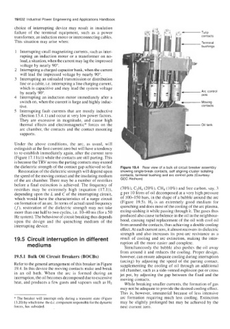
the dielectric strength of the contact gap achieved so far. Figure 19.4 Rear view of a bulk oil circuit breaker assembly
Restoration of the dielectric strength will depend upon showing single-break contacts, self aligning cluster isolating
the speed of the moving contact and the insulating medium contacts, terminal bushing and arc control pots (Courtesy:
of the arc chamber. There may be a number of restrikes GEC Alsthom)
before a final extinction is achieved. The frequency of
restrikes may be extremely high (equation (17. l)), (70%), C2H4 (20%), CH4 (10%) and free carbon, say, 3
depending upon the L and C of the interrupting circuit, g per 10 litres of oil decomposed at a very high pressure
which would have the characteristics of a surge circuit of 100-150 bars, in the shape of a bubble around the arc
on formation of an arc. In terms of actual rated frequency (Figure 19.5). H2 is an extremely good medium for
(f), restoration of the dielectric strength may not take quenching and does most of the cooling of the arc plasma,
more than one half to two cycles, i.e. 10-40 ms (for a 50 exting-uishing it while passing through it. The gases thus
Hz system). The behaviour of circuit breaking thus depends produced also cause turbulence in the oil in the neighbour-
upon the design and the quenching medium of the hood, causing rapid replacement of the oil with cool oil
interrupting device. from around the contacts, thus achieving a double cooling
effect. At each current zero, it almost recovers its dielectric
strength and also increases its post-arc resistance as a
19.5 Circuit interruption in different result of cooling and arc extinction, making the inter-
mediums ruption all the more easier and complete.
Simultaneously the bubble also pushes the oil away
from around it and reduces the cooling. Proper design,
19.5.1 Bulk Oil Circuit Breakers (BOCBs) however, can ensure adequate cooling during interruption
(arcing) by adjusting the speed of the parting contact,
Refer to the general arrangement of this breaker in Figure supplementing the cooling of oil through an additional
19.4. In this device the moving contacts make and break oil chamber, such as a side-vented explosion pot or cross
in an oil bath. When the arc is formed during an jet pot, by adjusting the gap between the fixed and the
interruption, the oil becomes decomposed due to excessive moving contacts.
heat, and produces a few gases and vapours such as H2 While breaking smaller currents, the formation of gas
may not be adequate to provide the desired cooling effect.
This is, however, immaterial because of less intensive
* The breaker will interrupt only during a transient state (Figure arc formation requiring much less cooling. Extinction
13.20) by which time the d.c. component responsible for the dynamic may be slightly prolonged but may be achieved by the
forces, has subsided. next current zero.