Page 672 - Industrial Power Engineering and Applications Handbook
P. 672

Circuit interrupters  19/637
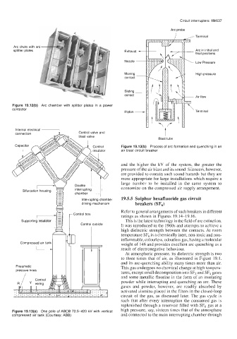
                                                                          Arc probe
                                                                            ,/       Terminal

       Arc  chute with arc
       splitter plates                                                               Arc in initial and
                                                                                     final positions
                                                                                     Low Pressure

                                                                                     High pressure


                                                                                     Air flow

      Figure 19.12(b)  Arc  chamber with  splitter  plates in a  power
      contactor                                        Piston -                      Terminal


        Internal electrical                                             t
        connection                 Control valve and
                                   blast valve
                                                                     Blast tube
                                         Control     Figure 19.13(b)  Process of  arc formation and quenching in an
                                         insulator   air blast circuit  breaker

                                                     and  the  higher  the  kV  of  the  system,  the  greater  the
                                                     pressure of the air blast and its sound. Silencers, however,
                                                     are provided to contain such sound hazards but they are
                                                     more appropriate for large installations which require a
                                 Double A            large  number  to  be  installed  in  the  same  system  to
                                 interrupting        economize on the compressed air supply arrangement.
                                 chamber
                                    Interrupting chamber   19.5.5 Sulphur hexafluoride gas circuit
                                    driving mechanism      breakers (SF,)
                                                     Refer to general arrangements of such breakers in different
                                                     ratings as shown in Figures  19.14-19.16.
                                                       This is the latest technology in the field of arc extinction.
                                                     It was introduced in the 1960s and attempts to achieve a
                                                     high  dielectric strength between  the contacts. At room
                                                     temperature SF6 is a chemically inert, non-toxic and non-
                                                     inflammable, colourless, odourless gas, having a molecular
          Compressed air tank                        weight of 146 and provides excellent arc quenching as a
                                                     result of electronegative behaviour.
                                                       At atmospheric pressure, its dielectric strength is two
                                                     to three times  that  of  air, as illustrated  in Figure  19.1,
                                                     and its arc-quenching ability many times more than air.
        Pneumatic                                    This gas undergoes no chemical change at high tempera-
                                                     tures, except small decomposition into SF2 and SF,  gases
                                                     and some metallic fluorine in the form of an insulating
                                                     powder while interrupting  and quenching an arc. These
                                                     gases  and  powder,  however,  are  readily  absorbed  by
                                                     activated alumina placed in the filters in the closed-loop
                                                     circuit  of  the  gas,  as  discussed  later. The gas cycle  is
                                                     such that  after every  interruption  the  consumed  gas is
                                                     replenished  through  a reservoir filled with SF6 gas at a
      Figure 19.13(a)  One pole of ABCB 72.5-420 kV with vertical   high pressure,  say, sixteen times that of the atmosphere
      compressed air tank  (Courtesy: ABB)           and connected to the main interrupting chamber through
   667   668   669   670   671   672   673   674   675   676   677