
Page 674 - Industrial Power Engineering and Applications Handbook
P. 674
Circuit interrupters 19/639
the conductivity of the arc plasma. (See also Section
19.3.) This quickly immunizes the free electrons, restores
its dielectric strength, quickly quenches the arc plasma,
extinguishes the arc and builds up the dielectric strength
after a current zero. After a current zero, the process
quickly, quenches the arc in the beginning itself by
sweeping away the arc plasma, thus improving the dielectric
strength between the parting contacts and achieving
successful extinction of the arc. The arc extinction process
may be slightly delayed when the contacts open very
close to the next current zero, and the quenching medium
blows it out with force, before the current zero, leading
to a case of current chopping. But with continuous
improvement in the techniques of arc extinction, it has
been possible to achieve an interruption devoid of acurrent
chopping or a restrike of the arc plasma.
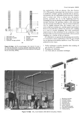
1. Interrupter unit 5. Operating mechanism As noted above, to quench the arc plasma successfully
2. Multi-shed insulator 6. Coupler it is essential to create a turbulence in the SF6 gas around
3. Base tube 7. Operating rod
4. Hydraulic storage cylinder 8. Control unit the arc plasma to destabilize and blow it out. This can be
achieved in two ways:
(a)
1 Puffer technique (a puffer identifies the exhaling of
Figure 19.16(a) An SF6 circuit breaker 123-145 kV, 31.5 kA. It
can also be pneumatic or spring operated, depending upon the gas forcibly by compression)
arc quenching technique adopted and energy required to extinguish 2 Rotating arc technique
the arc (Courtesy: BHEL) 3 Arc blast and arc assistance technique.
1 - Breaking chamber
2 - Central housing
3 - insulating column
4 - Insulating rod
5 - Opening spring
6 - Lower housing
7 - SF6 monitoring block
8 - Operating mechanism
9 - Closing spring
Figure 19.16(b) SF6 circuit breakers 300-500 kV (Courtesy: Alstom)