
Page 676 - Industrial Power Engineering and Applications Handbook
P. 676
Circuit interrupters 191641
The events are so fine-tuned and the size of chamber,
pressure of gas, travel, distance of the moving contact
and the size of blast nozzle so designed and adjusted that
a near-strike-free interruption can be achieved for low
reactive currents (inductive or capacitive) as well as full-
load and very heavy fault currents. The advance com-
pression of gas through the movement of main contact
plays an important role by storing a part of the gas even
before opening of the arcing contacts.
At high instantaneous currents the arc may occupy
most of the contact area between the arcing contacts and
may impede the flow of gas through the arc plasma. This
phenomenon is termed the clogging effect, but it assists
arc extinction in the following manner.
The gas around the arc plasma takes away a part of its
heat by radiation. At high temperatures, the gas loses its
specific gravity, becomes light weight and diminishes in
momentum (- mu2). As a result, the gas is rendered
incapable of penetrating through the arc plasma to quench
it. The flow of gas through the thick of the arc plasma is
thus impeded.
As the moving contact moves away, so the arc plasma
elongates, losing its initial intensity, and as it approaches
the current zero, it loses the most of it. The gas, on the
other hand, cools and regains its lost mass, while its
pressure in the chamber continues to build to its optimum
level, making it more capable of extinguishing a less
severe arc plasma. The interrupter can thus be adjusted
to blow out the arc at the first current zero, while clearing
heavy to very heavy fault currents.
Similarly, at lower currents, the volume of arc plasma
is too small (- Z2) and so is the clogging effect. The
pressure and volume of the quenching gas can be adjusted
to interrupt the current now also at current zero. All these
adjustments are pre-set and sealed by the manu-facturer.
Since the arc extinction technique is highly effective
and quick and occurs when the arcing contact is still
moving, arc length and hence contact travel, can be
reduced as can the arc energy and the excessive heating
as well as erosion of the arcing contacts. An extended
contact life can thus be achieved by this technique.
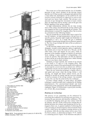
In lower voltage ratings, as noted above, the puffer
technique is quite prevalent and is adopted by all leading
manufacturers. For constructional details and more
1. Fibre glass arc chamber tube information on this mechanism, refer to the manufacturers’
2. Lower pole head catalogues. Figure 19.18 illustrates a typical pole assembly
3. Cap of a 12 kV, SF6 circuit breaker.
4. Gas filling valve
5. Main fixed contact
6. Fixed arcing contact Rotating arc technology
7. Moving contact arrangement
8. Moving arcing contact The process of arc quenching can be enhanced by
9. Blast nozzle
IO. Expansion chamber increasing the turbulence by ionizing more gas atoms, to
11. Lower contact increase the gas pressure and therefore turbulence. This
12. Lower terminal is possible by bringing more gas into contact with the
13. Top terminal
14. Spline shaft lever arc plasma, and this can be achieved by rotating the arc
15. Switching lever plasma between the contacts and displacing the arc by a
16. Two level pressure switch magnetic blow-out. A general method of achieving this
-1 st level contact for alarm
-2nd level contact for trip and lockout is by providing an electromagnetic field around the fixed
17. Enclosure for alumina contact, which gives the required rotating motion to the
18. Explosion proof safety valve arc plasma, when the moving contact moves away from
the fixed contact, as illustrated in Figure 19.19, similar
Figure 19.18 Cross-sectional view of a pole of a 12-36 kV SF,
breaker (Courtesy: NGEF Ltd.) to a motoring action. Figure 19.20 illustrates one pole of