
Page 677 - Industrial Power Engineering and Applications Handbook
P. 677
19/642 Industrial Power Engineering and Applications Handbook
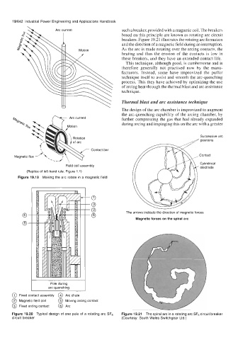
such a breaker, provided with a magnetic coil. The breakers
based on this principle are known as rotating arc circuit
breakers. Figure 19.21 illustrates the rotating arc formation
and the direction of a magnetic field during an interruption.
As the arc is made rotating over the arcing contacts, the
heating and thus the erosion of the contacts is low in
these breakers, and they have an extended contact life.
This technique, although good, is cumbersome and is
therefore generally not practised now by the manu-
facturers. Instead, some have improvized the puffer
technique itself to assist and smooth the arc-quenching
process. This they have achieved by optimizing the use
of arcing heat through the thermal blast and arc assistance
technique.
Thermal blast and arc assistance technique
The design of the arc chamber is improvized to augment
the arc-quenching capability of the arcing chamber, by
further compressing the gas that had already expanded
during arcing and impinging this on the arc with a greater
Successive arc
positions
Contact bar
Cylindrical
Field coil assembly ’ electrode
(Replica of left-hand rule, Figure 1.1)
Figure 19.19 Making the arc rotate in a magnetic field
0- The arrows indicate the direction of magnetic forces
Magnetic forces on the spiral arc
0-
Pole during I
arc quenching
@ Fixed contact assembly @ Arc chute
@ Magnetic field coil @ Moving arcing contact
@ Fixed arcing contact @ Arc
Figure 19.20 Typical design of one pole of a rotating arc SF6 Figure 19.21 The spiral arc in a rotating arc SF6 circuit breaker
circuit breaker (Courtesy: South Wales Switchgear Ltd.)