
Page 682 - Industrial Power Engineering and Applications Handbook
P. 682
Circuit interrupters 19/647
level in the arc chamber of the interrupting device, the
arc may restrike again and cause higher TRVs. This shall
further complicates the process of interruption and
extinction of the arc. See Blower et al. (1979), Telander
et al. (1986) and IEEE transactions (1977).
Note
The surge frequency at which the TRV will restrike will be extremely
high. It may be of the order of 1ClOO kHz, depending upon the
circuit constants L and C. To interrupt such high-frequency currents
is difficult for an ordinary breaker. But with the use of high
technologies, such as adopted in SF6 and VCB interrupting devices,
which make them fast operating (for arcing time see, Table 19.1),
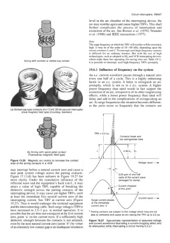
Arcing with contrate or slotted cup contact
it is possible to interrupt, such high-frequency TRVs promptly.
19.6.1 Influence of frequency on the system
An a.c. current waveform passes through a natural zero
every one half of a cycle. This is a highly redeeming
factor in an a.c. system. It helps to extinguish an arc
promptly, which is not so in a d.c. system. A higher
power frequency than rated would in fact support the
extinction of an arc, irrespective of its other magnetizing
effects, while a lower power frequency than rated will
delay and add to the complications of extinguishing an
arc. At surge frequencies the situation becomes different,
as the zeros occur so frequently that the contacts are
(a) Slotted cup type contacts of a 7.2 kV, 25 kA vacuum interrupter
(Axial magnetic field type) (Courtesy: Siemens) p
ill1
Ill1
TRV = 2.5 pu. 1
Contacts break and
arc extinguishes here
*
(b) Arcing with spiral petal contact
(Transverse magnetic field type)
Figure 19.26 Magnetic arc control to increase the contact I I I I
area of the arcing contacts in a VCB I I Voltage wave --e
I I
may interrupt before a natural current zero and cause a
near peak system voltage across the parting contacts. I . I . 0.02 part of one half
Figure 17.11(d) has been redrawn in Figure 19.27 for I I cycle of the current wave
more clarity. Under the cumulative influence of the I (enlarged for clarity)
reflected wave and the equipment’s back e.m.f., it may
attain a value of high TRV, capable of breaking the
dielectric strength across the parting contacts of the
interrupting device. It may cause yet higher TRVs, until
at least the immediate first natural current zero of the Current wave-
interrupting current. See TRV at current zero (Figure
19.27). Thus it would endanger the terminal equipment at the immediate
and the interconnecting cable. Such surge voltages (TRVs) current zero ‘a’
have increased to 2.5-3 p.u. in normal operation. It is
possible that the arc does not extinguish at the first current * Parting contacts are subject to this voltage which they are not
able to withstand and cause an arc raising the TRV up to 2.5 pu
zero, point ‘a’ on the current wave. If a sufficiently high
dielectric strength between the contacts is not attained, Figure 19.27 Approximate representation of assumed voltage
even by the next natural current zero (point ‘b’) by virtue and current waveforms illustrating a current-chopping effect and
of an extremely low contact gap or an inadequate insulation its attenuation while interrupting a circuit having 0.3 p.f.