
Page 699 - Industrial Power Engineering and Applications Handbook
P. 699
Temporary overvoltages and system grounding 201659
20.1 Theory of overvoltages
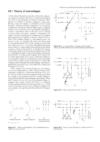
A three-phase balanced system has all the three phasors
of voltage and current 120" apart. as illustrated in Figure
20. I (a) for a conventional anti-clockwise rotation. These
phasors are known as positive sequence components.
During a fault. this balance is disturbed and the system
becomes unbalanced being composed of two balanced
components, one positive and the other negative sequence
(Figures 20.l(a) and (b)). For a description of the efiects
of these components, refer to (Section 12.2(v)). During
a ground fault, zero phase sequence components also
appear, which are single phasor components and combine
three equal phasors in phase, hown in Figure 20. I (c).
This is the residual voltage, Vg, that appears across the
ground circuit, i.e. between the neutral and the ground
as illustrated in Figure 20.12. This voltage is responsible
for a fault current, I, . Is will flow through the grounded
neutral when it is a three-phase four-wire neutral grounded Figure 20.2 An ungrounded or isolated neutral system
(circuit completing through the ground leakage capacitances)
system, as shown in Figure 20.12. It will also flow through
a thrce-phase three-wire artificially grounded system when
it is $rounded through a neutral grounding transformer
(Section 20.9.1 ) as illustrated in Figures 20.17 and 20.18.
In a three-phase three-wire system, which has neither its
own grounded neutral nor an artificially created grounded
neutral. there will be no direct ground fault current. But
charging currents through the ground leakage capacitances,
particularly on an HT system, may still exist, as illustrated
in Figures 20.2-20.3.
These currents may develop dangerous overvoltages
across the healthy phases, under certain ground circuit
impedance conditions, as discussed in Section 20.2. I( 1).
It is thus possible to encounter a ground fault, even when
the system is not grounded, the fault current finding its
return path through the ground leakage capacitances. While
an LT system. in view of a far too low ground voltage, V,
(equal to line voltage, Section 20.2.1( I)), as compared
to high ground capacitive leakage reactance. Xcg. would
cause a near open circuit (V,/X,, being too meagre) and
stay immune. leaving the grounded conductor floating at
v, = v, Figure 20.3 Case of ground fault within the load
v
v
v
B -__
45436
vlt -2% 1 I 1 N
) L V R v>/
Y iV YV
(a) (b) (C)
Positive sequence Negative sequence Zero sequence or
residual quantities ', =G
v, = v, = v, = v -t
Figure 20.1 Phasor representation of an unbalanced power Figure 20.4 Case of a ground fault on a power system on
system on a ground fault the load side