
Page 702 - Industrial Power Engineering and Applications Handbook
P. 702
201662 Industrial Power Engineering and Applications Handbook
lnfe ren ce (ii) Ferro-resonance effect
This is same as for resistive impedance. In these two The above analysis of overvoltages in the healthy phases
cases, when the external impedance is resistive or of an ungrounded system in the event of a ground fault
capacitive, there is no excessive voltd e rise across the on one of the phases was based on the assumption that
healthy phases ofthe system beyond &V(, The voltage the inductive reactance of the electromagnetic circuit,
developed across the ground capacitance, Xce, and the Le. the magnetic core of the connected equipment (which
external impedance R or X, is shared in the ratio of their may be a transformer or an induction motor) was linear
own values, the sum total of which will remain constant over its entire range of operation. But this may not always
at Av(. be true. It is also possible that some components such as
a CT or a CVT, may have their magnetic core gradually
(2) When the external impedance is an inductive saturated* during normal operation, under certain circuit
reactance conditions and resonate with the ground capacitive
reactance Xcg. This may lead to a high voltage in a healthy
Now the situation is different, as resonance and ferro- system, even when there is no ground fault, the ground
resonance effects in the series inductive-capacitive circuits circuit becoming completed through the grounded neutral
may cause dangerous overvoltages. of such a device (Figure 20.8).
(i) Resoizaizce effect
Referring to Figure 20.5, the peak voltage Vi across XL R
will be
Y
V,',,'!, = xL ' fiV( (20.3) B
x,, -xL
Computing Vi along similar lines to those for resistive
impedance,
i.e when XL = 0 V,',,,,, = 0
'Clt, kr
XI, = Xcp, V,',,,,,will tend to approach infinity
This is known as a resonating condition. It is, however,
seen that in view of some in-built impedance in the ground
circuit it will tend to attenuate the alarmingly risin voltage
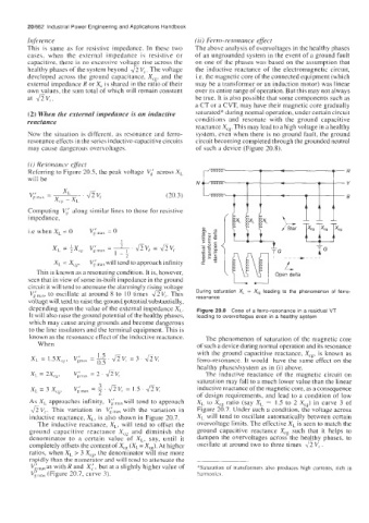
Vil,,,;,, to oscillate at around 8 to IO times dV,. This During saturation X, 1 Xcg leading to the phenomenon of ferro-
resonance
voltage will tend to raise the ground potential substantially,
depending upon the value of the external impedance X,. Figure 20.8 Case of a ferro-resonance in a residual VT
It will also raise the ground potential of the healthy phases, leading to overvoltages even in a healthy system
which may cause arcing grounds and become dangerous
to the line insulators and the terminal equipment. This is
known as the resonance effect of the inductive reactance. The phenomenon of saturation of the magnetic core
When of such a device during normal operation and its resonance
with the ground capacitive reactance, Xcg, is known as
ferro-resonance. It would have the same effect on the
healthy phases/systein as in (i) above.
The inductive reactance of the magnetic circuit on
saturation may fall to a much lower value than the linear
inductive reactance of the magnetic core, as a consequence
of design requirements, and lead to a condition of low
As X,> approaches infinity, Vilndxwill tend to approach XL to Xcs ratio (say XL = 1.5 to 2 Xcg) in curve 3 of
&V,, This variation in V$,,, with the variation in Figure 20.7. Under such a condition, the voltage across
inductive reactance, X,, is also shown in Figure 20.7. X, will tend to oscillate automatically between certain
The inductive reactance, XL, will tend to offset the overvoltage limits. The effective X, is seen to match the
ground capacitive reactance X,, and diminish the ground capacitive reactance Xcg such that it helps to
denominator to a certain value of X,, say, until it dampen the overvoltages across the healthy phases, to
completely offsets the content of Xcr (X,= Xcg). At higher oscillate at around two to three times aV,.
ratios, when XL > 3 Xcg, the denominator will rise more
rapidly than the numerator and will tend to allmuate the
V,'lndxa~ with R and X:, but at a slightly higher value of *Saturation of transformel-s also produces high currents, rich in
Vinlax (Figure 20.7, curve 3). harmonics.