
Page 707 - Industrial Power Engineering and Applications Handbook
P. 707
Temporary overvoltages and system grounding 20/667
To achieve the desired conditions of grounding, the 0
following are the generally adopted grounding practices.
7
20.6.1 An ungrounded or isolated neutral system
When the system is totally isolated from the ground circuit, 6
except through indicating, measuring or protective devices,
which are normally grounded and possess a high
impedance to ground, the ground fault factor 5 1:
uo 3
This may become higher, depending upon the circuit's
conditions (for example, the ferro-resonance effect,
Section 20.2.1.2). 2
20.6.2 A grounded neutral system 1
When the system is grounded through its neutral, either 0
solidly through a resistance or through an arc suppression 1 2 3 X,,/Xl - 6 7 %
5
4
coil (inductor), it becomes a grounded neutral system.
This type of system grounding may be classified as
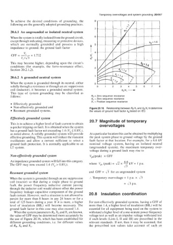
follows: R,, = Zero sequence resistance
X,, = Zero sequence reactance
Xl = Positive sequence reactance
Effectively grounded
Non-effectively grounded and Figure 20.16 Relationship between RdX1 and XdX, to determine
Resonant grounded systems. the values of ground fault factor kg based on IEC
Effectively grounded system
20.7 Magnitude of temporary
This is to achieve a higher level of fault current to obtain ove rvo I t ag es
a quicker tripping on fault. It is obtained when the system
has a ground fault factor not exceeding 1.4 ( Vg I O.SV,),
as noted above. A solidly grounded system will provide At a particular location this can be obtained by multiplying
effective grounding. This system will reduce the transient the peak system phase to ground voltage by the ground
oscillations and allow a current sufficient to select a fault factor at that location. For example, for a 6.6 kV
ground fault protection. It is normally applicable to an nominal voltage system, having an isolated neutral
LT system. (ungrounded system), the maximum temporary over-
voltage during a ground fault may rise to
Non-effectively grounded system Vph(peak) x GFF
An impedance grounded system will fall into this category. 6.6
a
The GFF may now exceed 1.4 (Vg > 0.8Ve). where Vph (peak) = fi x - kV = 1 p.u.
Resonant grounded system and GFF = for an ungrounded system
When the system is grounded through an arc suppression :. Temporary overvoltage = 1 pa. x 8
coil (reactor) so that during a single phase to ground = 4p.u.
fault, the power frequency inductive current passing
through the inductor coil would almost offset the power
frequency leakage capacitive component of the ground
fault current. However, such a situation is not allowed to 20.8 Insulation coordination
persist for more than 8 hours in any 24 hours or for a
total of 125 hours during a year. If it is more, a higher For non-effectively grounded systems, having a GFF of
level of insulation (BIL) will become necessary. The more than 1.4, a higher level of insulation (BIL) will be
ground fault factor in this case may also exceed 1.4. essential for all equipment being used on the system to
When the system parameters Ro, Xo and XI are known, withstand a higher level of a one-minute power frequency
the value of GFF may be determined more accurately by voltage test as well as an impulse voltage withstand test
the use of Figure 20.16, which has been established for if such levels (Lists I, I1 and 111) are prescribed in the
different grounding conditions, Le. for different values relevant standards. If not, then it may be assumed, that
of Ro. Xo and XI. the prescribed test values take account of such an