
Page 711 - Industrial Power Engineering and Applications Handbook
P. 711
Temporary overvoltages and system grounding 20/671
and Table 13.6). As a result, the ground fault current in
a generator circuit is greater than its three-phase symme-
trical fault current. This current rises further when all of
them are individually grounded and more than one unit
os z,, V,? n (20.6) are running in parallel at a time. It is worth mentioning
=
11, 1000. kVA that when two or more generators are running in parallel
From this equation one can determine the required and all of them are grounded, they form a closed circuit
calue of neutral circuit impedance for a particular to cause circulating currents. This may occur even in a
level of ground fault current. The external impedance healthy system due to unbalance, not because of single-
will be Z,, less the ground impedance. In HT systems phase loads but unequal generator phase currents due to
one can also determine the likely value of a ground eddy currents. These are important aspects and must be
inductor coil to achieve a near-resonance condition, considered while deciding on the grounding method of a
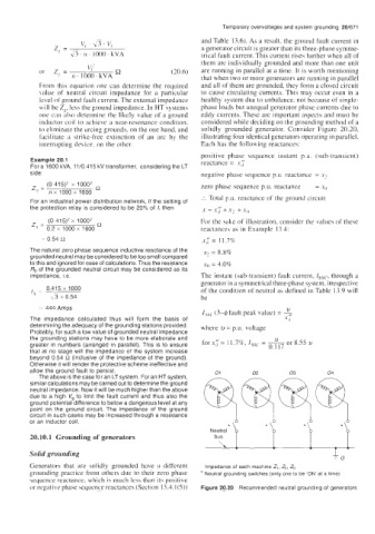
to eliminate the arcing grounds, on the one hand, and solidly grounded generator. Consider Figure 20.20,
facilitate a strike-free extinction of an arc by the illustrating four identical generators operating in parallel.
interrupting device, on the other. Each has the following reactances:
positive phase sequence instant p.u. (sub-transient)
Example 20.1 reactance = XC
For a 1600 kVA, 11/0.415 kV transformer, considering the LT
side negative phase sequence p.u. reactance = x2
z, (0 415)' x 1000' zero phase sequence p.u. reactance = xo
=
nx1000x1600
:. Total p.u. reactance of the ground circuit
For an industrial power distribution network, if the setting of
the protection relay is considered to be 20% of I, then
s = x;' + X? + .Xg
z- (0 415)'~ 10002 ~I For the sake of illustration, consider the values of these
' - 0 2 x 1000 x 1600 reactances as in Example 13.4:
= 0 54 CL xy = 11.7%
The natural zero phase sequence inductive reactance of the x2 = 8.89
grounded neutral may be considered to be too small compared
to this and ignored for ease of calculations Thus the resistance = 4.0%
Ro of the grounded neutral circuit may be considered as its
impedance, i e The instant (sub-transient) fault current, lssc, through a
generator in a symmetrical three-phase system, irrespective
0 415 x 1000
I, = of the condition of neutral as defined in Table 13.9 will
L3 x 0 54 be
== 444 Amps V
list (3-$ fault peak value) =
The impedance calculated thus will form the basis of 21 <I
determining the adequacy of the grounding stations provided. where v = p.u. voltage
Probably, for such a low value of grounded neutral impedance
the grounding stations may have to be more elaborate and for x;' = 11.7%, I,,, = - or 8.55 v
greater in numbers (arranged in parallel). This is to ensure 0.1 17
that at no stage will the impedance of the system increase
beyond 0.54 R (inclusive of the impedance of the ground).
Otherwise it will render the protective scheme ineffective and
allow the ground fault to persist. G1 G2 G4
The above is the case for an LT system. For an HT system,
similar calculations may be carried out to determine the ground
neutral impedance. Now it will be much higher than the above
due to a high Vg to limit the fault current and thus also the
ground potential difference to below a dangerous level at any
point on the ground circuit. The impedance of the ground
circuit in such cases may be increased through a resistance
or an inductor coil. Neutral* $ * $ *)
20.10.1 Grounding of generators bus *$
Solid grounding
-G
Generators that are solidly grounded have a different Impedance of each machine Z,, Z,, Z,
grounding practice from others due to their zero phase * Neutral grounding switches (only one to be 'ON' at a time)
sequence reactance. which is much less than its positive
or negative phase sequence reactances (Section 13.4.1(5)) Figure 20.20 Recommended neutral grounding of generators