
Page 714 - Industrial Power Engineering and Applications Handbook
P. 714
201674 Industrial Power Engineering and Applications Handbook
.. 12 = 682 A
and required secondary resistance
R=g /gr = 10 A
682 I, = i,, + 3. icc
= 0.32 R
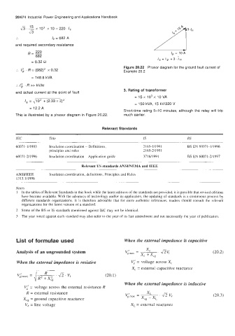
Figure 20.22 Phasor diagram for the ground fault current of
... /ir (682)' x 0.32 Example 20.2
R =
= 148.8 kVA
:. Iir R >> kVAr
3. Rating of transformer
and actual current at the Doint of fault
= 15 x lo3 x 10 VA
I, = 2/10' + (2.33 x 3)'
= 150 kVA. 15 kVl220 V
,~
= 12.2A
Short-time rating 5-10 minutes, although the relay will trip
This is illustrated by a phasor diagram in Figure 20.22. much earlier.
Relevant Standards
IEC Title IS BS
6007 1 - 1/1993 Insulation coordination - Definitions, 2 165- 1/1991 BS EN 60071-1/1996
principles and rules 21 65-2/199 1
60071-2/1996 Insulation coordination - Application guide 37 16/199 1 BS EN 60071-2/1997
Relevant US standards ANSVNEMA and IEEE
~~ ~~
ANSVIEEE Insulation coordination, definitions, Principles and Rules
13 13.1/1996
__ . ~~
Notes
1 In the tables of Relevant Standards in this book while the latest editions of the standards are provided, it is possible that revised editions
have become available. With the advances of technology and/or its application, the updating of standards is a continuous process by
different standards organizations. It is therefore advisable that for more authentic references, readers should consult the relevant
organizations for the latest version of a standard.
2 Some of the BS or IS standards mentioned against IEC may not be identical.
3 The year noted against each standard may also refer to the year of its last amendment and not necessarily the year of publication.
List of formulae used When the external impedance is capacitive
Analysis of an ungrounded system (20.2)
When the external impedance is resistive Vi = voltage across X,
X, = external capacitive reactance
(20.1)
When the external impedance is inductive
Vi = voltage across the external resistance R
R = external resistance (20.3)
Xcg = ground capacitive reactance
Ve = line voltage XL = external reactance