
Page 709 - Industrial Power Engineering and Applications Handbook
P. 709
Temporary overvoltages and system grounding 20/669
If the above are not taken into account the devices Note
and components used on the system may have to be The magnetic core is designed so that it will not jaturate during
selected or braced for a higher system voltage, say, up to normal operation to avoid a ferro-resonance condition. The knee
twice the rated voltage or even more. The overvoltage point voltage is kept at about I .3 times the system line voltage.
condition may almost be the same as for ungrounded
capacitor switching (Section 23.5.1 (ii)).
Residual voltage transformer (star/open delta
Neutral grounding transformers trans former)
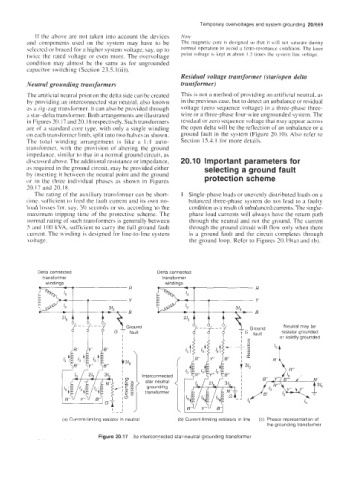
The artificial neutral point on the delta side can be created This is not a method of providing an artificial neutral. as
by providing an interconnected star neutral, also known in the previous case, but to detect an unbalance or residual
as a iig-zag transformer. It can also be provided through voltage (zero sequence voltage) in a three-phase three-
a star-delta transformer. Both arrangements are illustrated wire or a three-phase four-wire ungrounded system. The
in Figures 20.17 and 20.18 respectively. Such transformers residual or zero sequence voltage that may appear across
are of a standard core type, with only a single winding the open delta will be the reflection of an unbalance or a
on each transformer limb, split into two halves as shown. ground fault in the system (Figure 20.10). Also refer to
The total winding arrangement is like a 1:1 auto- Section 15.4. I for more details.
transtormer, with the provision of altering the ground
impedance, similar to that in a normal ground circuit, as
discussed above. The additional resistance or impedance, 20.1 0 Important parameters for
as required in the ground circuit, may be provided either selecting a ground fault
by inserting it between the neutral point and the ground
or in the three individual phases as shown in Figures protection scheme
20.17 and 20.18.
The rating of the auxiliary transformer can be short- 1 Single-phase loads or unevenly distributed loads on a
time. sufficient to feed the fault current and its own no- balanced three-phase system do not lead to a faulty
load losses fot, say, 30 seconds or so, according to the condition as a result of unbalanced currents. The single-
maximum tripping time of the protective scheme. The phase load currents will always have the return path
normal rating of such transformers is generally between through the neutral and not the ground. The current
5 and 100 kVA, sufficient to carry the full ground fault through the ground circuit will flow only when there
current. The winding is designed for line-to-line system is a ground fault and the circuit completes through
voltage. the ground loop. Refer to Figures 20.19(a) and (b).
Delta connected Delta connected
transformer transformer
windings windinas
(a) Current-limiting resistor in neutral (bj Current-limiting resistors in line (c) Phasor representation of
the grounding transformer
Figure 20.17 36 interconnected star-neutral grounding transformer