
Page 704 - Industrial Power Engineering and Applications Handbook
P. 704
20/664 Industrial Power Engineering and Applications Handbook
A three-phase four-wire system may be grounded in
the following ways:
N
1 Solid neutral grounding system or
2 Impedance neutral grounding system
B
20.4.1 Solid neutral grounding system (also
known as effectively grounded system)
Residual We have already discussed a solid neutral grounding
voltage system in Section 20.3. The residual volta e or the ground
transformer potential rises to the phase voltage Vt/& and does not
(RW alter the voltage of the healthy phases. To analyse this
system, we have redrawn the circuit of Figure 20.2 in
Figure 20.12, grounding the neutral solidly. The impedance
to ground, Zg, through the neutral circuit will be extremely
small and resistive in nature, compared to the ground
capacitive reactance Xcg, i.e. Zg << Xcg, and will share
Residual voltage Vg = 3 most of the fault current. The current through the ground
6 leakage capacitances may be ignored to derive an easy
inference. The effectiveness of grounding and its
Figure 20.10 Detecting a ground fault in an isolated neutral impedance will play the most decisive role in determining
system
the fault current and the rnost appropriate protection.
Then the total impedance through the ground circuit 20.4.2 Impedance neutral grounding system
+
2, = 2, + z, 2" Consider the system shown in Figure 20.12 and introduce
some impedance Zq in its neutral circuit as shown in
and the fault current through ground circuit Figure 20.13. Now it is possible to vary the magnitude
3 ", and characteristic of the fault current through the neutral
I =- circuit.
z,
If Ig = ground fault current and
Zi = fault current through the healthy phases due to
neutral impedance Zg
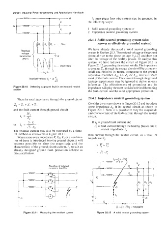
The residual current may also be measured by a three-
CT method as illustrated in Figure 20.11. then current through the neutral circuit, as a result of
When some extra impedance R, X,-, XL or a combina- impedance Z,,
tion of these is introduced into the ground circuit it will
become possible to alter the magnitude and the -_
characteristic of the ground circuit current, Ig, to suit an = I; + 1;
already designed ground fault protection scheme as
discussed below.
I, = I; + &I;
I, = I; + &I;
r A R
Direction of induced
current in the CTs. Y
8
= Negligible
I; + I; = &I; = Negligible
I; + I; = &I;
Figure 20.11 Measuring the residual current Figure 20.12 A solid neutral grounding system