
Page 705 - Industrial Power Engineering and Applications Handbook
P. 705
Temporary overvoltages and system grounding 20/665
With such a system the possibility of an arcing ground
is almost eliminated and it is now possible even to allow
the ground fault condition to prevail until it can be
conveniently repaired. Now it will cause no harm to a
human operator, supporting insulators or the terminal
equipment. On long-distance transmission or distribution
networks such a situation may rather be desirable to
prevent the system from tripping instantly until at least
the off-peak periods or until the supply is restored through
an alternative source. The process of finding the fault
and its repair may be allowed to take a little longer.
A neutral grounding reactor (NGR) is also desirable
to achieve auto-reclosing of a faulty phase during a one-
pole opening as a result of a fault of a transient nature on
this phase (Section 17.4.1). The reactance grounding will
limit the high unbalanced capacitive currents through
Z, = Tapped reactor or arc suppression coil
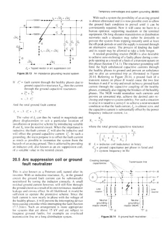
the healthy phases to ground and prevent an unbalance
Figure 20.13 An impedance grounding neutral system and so also an unwanted trip as illustrated in Figure
20.14. Referring to Figure 20.14, a ground fault of a
transient nature on phase B would cause the two line
If I," = fault current through the healthy phases due to breakers b and h' to trip and result in heavy ground fault
ground capacitive reactance Xce, then the current current through the capacitive coupling of the healthy
through the ground capacitive reactances
= c+ phases. The NGR would neutralize such currents and
phases, eventually also tripping the breakers ofthe healthy
prevent an unwanted trip, achieve the desired auto re-
= \3.1: closing and improve system stability. For such a situation
to arise it is tuned to a zero p.f. to achieve a near-resonant
And the total ground fault current condition so that the fault current, Ig, is almost zero, and
the capacitive current is substantially offset by the power
frequency inductor current, i.e.
The value of I, can thus be varied in magnitude and
phase displacement to suit a particular location of
installation or protective scheme by introducing suitable
R and X,~ into the neutral circuit. When the impedance is where the total ground capacitive reactance
inductive. the fmlt current 1; will also be inductivc and
will offset the ground capacitive current I:. In such a
grounding, the main purpose is to offset the fault current
as much as possible to immunize the system from the
haurds of an arcing ground. This is achieved by providing If L = inductor coil inductance in henry
an inductor coil. also known as an arc suppression coil, C,,= ground capacitance per phase in farad and
of a suitable value in the neutral circuit. f = system frequency in Hz
20.5 Arc suppression coil or ground Coupling (leakage)
fault neutralizer capacitances Transmission line
,
This is also known as a Petersen coil, named after its
inventor. With an inductive reactance, X,, in the ground \- i
circuit the ground fault current can be substantially
neutralized by tuning the inductor correctly. A small .R
residual ground current however, will still flow through t t t\
the ground circuit as a result of its own resistance, insulator
leakage and corona effect. In all likelihood, it would be ' P
44
I
sufficient to operate the protective scheme. Since the I 'I grounding Neutra:{ 1
fault current is now nearly in phase with the voltage of
the healthy phases, it will prevent the interrupting device grounding NeutralF
from causing a restrike while interrupting the fault (Section
17.7.2(iii)). Such an arrangement is more appropriate reactor (NGR) reactor (NGR)
for systems that are above 15 kV and are subject to
frequent ground faults, for example an overhead
transmission line or a long distribution system. Figure 20.14 A ground fault neutralizer