
Page 710 - Industrial Power Engineering and Applications Handbook
P. 710
201670 Industrial Power Engineering and Applications Handbook
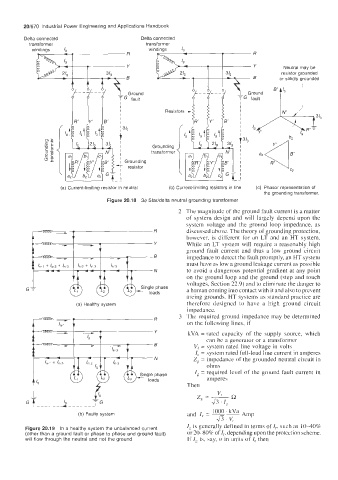
Delta connected Delta connected
transformer transformer
windings IQ windings 1,
Neutral may be
resistor grounded
or solidly grounded
(a) Current-limiting resistor in neutral (b) Current-limiting resistors in line (c) Phasor representation of
the grounding transformer
Figure 20.18 34 Staridelta neutral grounding transformer
2 The magnitude of the ground fault current is a matter
of system design and will largely depend upon the
system voltage and the ground loop impedance, as
discussed above. The theory of grounding protection,
however. is different for an LT and an HT system.
While an LT system will require a reasonably high
ground fault current and thus a low ground circuit
impedance to detect the fault promptly, an HT system
must have as low a ground leakage current as possible
to avoid a dangerous potential gradient at any point
on the ground loop and the ground (step and touch
voltages, Section 22.9) and to eliminate the danger to
G a human coming into contact with it and also to prevent
arcing grounds. HT systems as standard practice are
(a) Healthy system therefore designed to have a high ground circuit
impedance.
3 The required ground impedance may be determined
on the following lines, if
kVA = rated capacity of the supply source, which
can be a generator or a transformer
Vi = system rated line voltage in volts
I,. = system rated full-load line current in amperes
Zg = impedance of the grounded neutral circuit in
ohms
I, = required level of the ground fault current in
amperes
Then
= R
z, ~ "(
.\15 . I,
(b) Faulty system and I, = 1000 ' kVa Amp
47. v,
IF is generally defined in terms of Ir, such as 1040%
Figure 20.19 In a healthy system the unbalanced current
(other than a ground fault or phase to phase and ground fault) or 20-80% of Ir, depending upon the protection scheme.
will flow through the neutral and not the ground If I, is, say, n in units of I, then