
Page 713 - Industrial Power Engineering and Applications Handbook
P. 713
Temporary overvoltages and system grounding 201673
will become as follows when all the four generators are recommended to limit the TRV by inserting a small
grounded and are operating in parallel and one of them resistance into the grounding circuit to make the ground
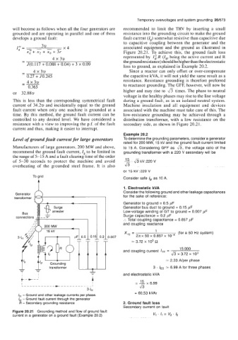
develops a ground fault: fault current (Ig) somewhat resistive than capacitive due
to capacitive coupling between the generator and the
3v
I"=- - - -x4 associated equipment and the ground as illustrated in
g
xz+ x2 + xo + 3r Figure 20.21. To achieve this, the ground fault loss
4 x 3v represented by R (Igr being the active current and R
-
- the ground resistance) should be higher than the electrostatic
J(O.117 + 0.088 + 0.04) + 3 x 0.09 loss to ground, as explained in Example 20.2.
- 4 x 3v Since a reactor can only offset or over-compensate
-
0.27 + 50.245 the capacitive kVA, it will not yield the same result as a
-- resistance. Resistance grounding is therefore preferred
4 x 3v
-
0.365 to reactance grounding. The GFF, however, will now be
or 32.88~ higher and may rise to fi times. The phase to neutral
voltage in the healthy phases may rise to the line voltage
This is less than the corresponding symmetrical fault during a ground fault, as in an isolated neutral system.
current of 34.2~ and incidentally equal to the ground Machine insulation and all equipment and devices
fault current when only one machine is grounded at a associated with the machine must take care of this. The
time. By this method, the ground fault current can be low-resistance grounding may be achieved through a
controlled to any desired level. We have considered a distribution transformer, with a low resistance on the
resistance with a view to improving the p.f. of the fault secondary side, as shown in Figure 20.21.
current and thus, making it easier to interrupt.
Example 20.2
Level of ground fault current for large generators To determine the grounding parameters, consider a generator
rated for 200 MW, 15 kV and the ground fault current limited
Manufacturers of large generators, 200 MW and above, to 15 A. Considering GFF as 6, the voltage ratio of the
recommend the ground fault current, Ig to be limited in grounding transformer with a 220 V secondary will be
the range of 5-15 A and a fault clearing time of the order
of 5-30 seconds to protect the machine and avoid 15, & kV:220 V
overheating of the grounded steel frame. It is also 6
or 15 kV:220 V
To grid
Consider safe /gr as 10 A.
1. Electrostatic kVA
Consider the following ground and other leakage capacitances
Generator
transformer for the sake of reference:
Generator to ground = 0.5 pF
Generator bus duct to ground = 0.15 pF
Low-voltage winding of GT to ground = 0.007 pF
Surge capacitance = 0.2 pF
:. Total coupling capacitance = 0.857 pF
and coupling reactance
x- 1 (for a 50 Hz system)
cg - 2n x 50 x 0.857 x lo4
= 3.72 x 10³ n
15 000
and coupling current IC, =
&i 3.72 x io3
x
= 2.33 Nper phase
3 . ICc = 6.99 A for three phases
and electrostatic kVA
I
x
I___________,________---l = 15 6.99
d3
3.1,
= 60.53 kVAr
I, - Ground and other leakage currents per phase.
Is, - Ground fault current through the generator
R - Secondary grounding resistance 2. Ground fault loss
Secondary current on fault
Figure 20.21 Grounding method and flow of ground fault
current in a generator on a ground fault (Example 20.2) v, * I, = v, . /2