
Page 706 - Industrial Power Engineering and Applications Handbook
P. 706
20/666 Industrial Power Engineering and Applications Handbook
then appropriate ground fault protective scheme as well as
the insulation level for that system. It is defined as the
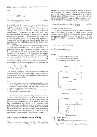
ratio of the highest voltage to ground, Vg (r.m.s.), of the
healthy phase or phases during a ground fault to the
corresponding power frequency phase voltage V, /&
or L 1 henry (20.4) when the system was healthy. Refer to Figure 20.15.
.
3(2~f)~ Cg
"E
:. Ground fault factor (GFF) = - (20.5)
It is likely that for reasons of system disturbances, v, 143
frequency fluctuations and switching of a few sections
of the system, both X, and Xcg may vary in actual operation which is usually more than 1.
and upsct the resonance condition, leading to transient It is also established that in an effectively grounded
overvoltages. To overcome this, the inductor coil may system the voltage to ground, Vg, of the healthy phases
be made variable (the setting of which may be altered does not exceed 80% of the line-to-line voltage V, and
automatically) through a motor-driven tap changer to consequently the GFF does not exceed 0.8 x 4, i.e.
achieve the tuning again. If the ground fault persists the 1.4. The system may be considered as effectively grounded
inductor coil may be rated continuously rather than for a when
short time and for the full fault current that the coil may
have to carry.
x+
To overcome the generation of overvoltages across o= between 0 and 3, and
the inductor coil (Section 20.2.1(2)) its inductance, L, is R
=
generally selected high, so that the resonance condition 2 between 0 and 1
with the ground capacitors, C,, occurs near the natural X+
frequency of the system (SO or 60 HL) and the voltage
developed across the inductor coil, Vi, may oscillate where
only at around Vel&. Generally, the Petersen coil Xo = zero sequence reactance
neutralizer is a high-reactance grounding and is also termed Ro = zero sequence resistance
resonant grounding, free from overvoltages and restrikes. X, = positive sequence reactance
Equating the voltages developed across the Petersen coil
R
The voltage developed would thus oscillate around the Y
normal voltage and fall in phase with the fault current to
achieve a near-strike-free interruption of the interrupting
device on a ground fault. 6
v, Id 3
Note --1
1 Aa in IEC 60071-1,Za higher insulation level (BIL) w~ll be
necessary for all insulators and terminal equipment when the
ground fault persists for more than 8 hours per 24 hours or a rG
total of more than 125 hours during a year.
2 Because of likely de-tuning and generation of overvoltages, (a) Healthy system
this system is seldom in practice.
Sometimes such a situation may arise on its own,
even on a normally grounded system, not intendcd for
ground current neutralizing. It can happen when an
overhead line snaps due to a storm, winds or any other
factor and falls on trees, hedges or dry metalled roads
and remains energized in the absence of a proper return
path and cause a low leakage current, insufficient to trip
the protective circuit. This is a situation not really desirable
on a normally grounded system, as it may lead to an
ungrounded system and may develop overvoltages. G =G
(b) Faulty system
20.6 Ground fault factor (GFF) R & Y - Healthy phases
6 - Faulty phase
V, - (rms) value of ground voltage measured on fault
This is an important indicator that shows the grounding
condition of a system and helps to determine the most Figure 20.15 Determining the ground fault factor