
Page 703 - Industrial Power Engineering and Applications Handbook
P. 703
Temporary overvoltages and system grounding 20/663
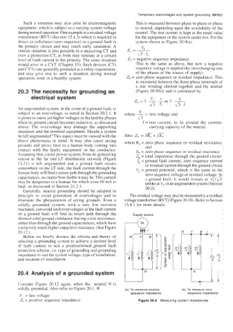
Such a situation may also arise in electromagnetic This is measured between phase to phase or phase
equipment, which is subject to a varying system voltage to neutral, depending upon the availability of the
during normal operation. One example is a residual voltage neutral. The test current is kept at the rated value
transformer (RVT) (Section 15.4.3) which is required to for the equipment or the system under test. For the
detect an unbalance (zero sequence) or a ground fault in system shown in Figure 20.9(a).
the primary circuit and may reach early saturation. A
similar situation is also possible in a measuring CT and z, =- VI
even a protection CT, as both may saturate at a certain v'3 ' I,
level of fault current in the primary. The same situation 22 = negative sequence impedance.
would arise in a CVT (Chapter 15). Such devices (CTs This is the same as above, but now a negative
and CVTs) are generally grounded as a safety requirement, sequence voltage is applied (by interchanging one
and may give rise to such a situation during normal of the phases of the source of supply)
operation, even in a healthy system. Zo = zero phase sequence or residual impedance. This
is measured between the three-phase terminals of
a star winding shorted together and the neutral
20.3 The necessity for grounding an (Figure 20.9(b)) and is calculated by
electrical system
An ungrounded system, in the event of a ground fault, is
subject to an overvoltage, as noted in Section 20.2.1. It where - V = test voltage and
is prone to cause yet higher voltages in the healthy phases 43
when its ground circuit becomes inductive, as discussed I = test current, to be around the current-
above. Thc ovcrvoltage may damage the supporting carrying capacity of the neutral.
insulators and the terminal equipment. Should a system
be left ungrounded? This aspect must be viewed with the Also Zo = 3% + 3%
abohe phenomena in mind. It may also cause arcing where Ro = zero phase sequence or residual resistance,
grounds and prove fatal to a human body coming into and
contact with the faulty equipment or the conductor. X, = zero phase sequence or residual reactance
Assuming that a total power system, from its generating Zg = total impedance through the ground circuit
station to the far end LT distribution network (Figure Ig = ground fault current, zero sequence current
13.21) is left ungrounded and a ground fault occurs or residual current through the ground circuit
somewhere on the LT side, the fault current through the Vg = ground potential, which is the same as the
human body will find a return path through the grounding zero sequence voltage or residual voltage. In
capacitances, no matter how feeble it may be. This current a ground fault, it would remain at v;/&
may be dangerous to a human for which even 10 mA is unlike at Vt in an ungrounded system (Section
fatal. as discussed in Section 21.2.1. 20.2).
Generally, neutral grounding should be adopted in
principle to avoid generation of overvoltages and to The residual voltage may also be measured by a residual
eliminate the phenomenon of arcing grounds. Even a voltage transformer (RVT) (Figure 20. IO). Refer to Section
solidly grounded system, with a very low resistive 15.4.1 for more details.
reactance, can avoid such overvoltages as the fault current
on a ground fault will find its return path through the Supply source
rather than through the ground capacitances, which have 4
shortest solid ground conductor, having a low resistance,
a relatively much higher capacitive reactance. (See Figure
20.12.)
Below we briefly discuss the critcria and theory of
selecting a grounding system to achieve a desired level
of fault current to suit a predetermined ground fault
protection scheme, i.e. type of grounding and grounding
impedance to suit the system voltage, type of installation,
and location of installation.
20.4 Analysis of a grounded system
Consider Figure 20.12 again, when the neutral N is I
solidly grounded. Also refer to Figure 20.1. If (a) To measure positive (b) To measure zero
sequence impedance sequence impedance
V, = line voltage
2, = positive sequence impedance Figure 20.9 Measuring system impedances