Page 701 - Industrial Power Engineering and Applications Handbook
P. 701

I  emporary overvoltages and system grounding 201661
                                                                          May attenuate at about 6-10  .  &v,


                                                                                       I
                   XcQ = Ground leakage capacitive reactance                      -  ?--
                   Z;  = Additional impedance (R, X,  or X,)
           Figure 20.5  Equivalent ground circuit  representing the power
           system of  Figure 20.2


                                                                    1      2           4     5
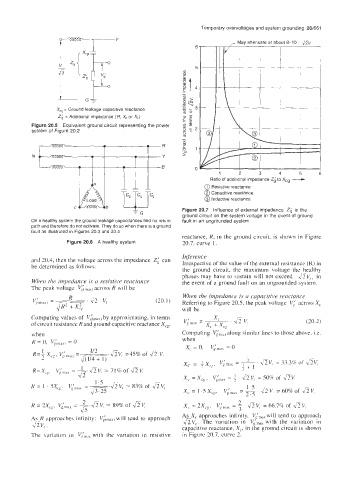
                                                                  Ratio of  additional impedance i'i  to Xcg --c
                                                                @ Resistive reactance
                                                                @ Capacitive reactance
                                                                @ Inductive reactance
                                                         Figure 20.7  Influence of external impedance  Zb  in the
                                                         ground circuit on the system voltage in the event of  ground
           On a healthy system the ground leakage capacitances find no return   fault  in an ungrounded system
           path and therefore do not activate. They do so when there is a ground
           fault as illustrated in Figures 20.3 and 20 4
                                                         reactance, R, in  the  ground  circuit. is  shown  in Figure
                      Figure 20.6  A healthy system      20.7, curve  1.

                                                         Inference
           and 70.4, then the voltage across the impedance  2; can
           be determined as follows:                     Irrcspcctive of the value of the external resistance (R) in
                                                         the  ground  circuit,  the  maximum  voltage  the  healthy
                                                         phases may have to sustain will  not  exceed  &V,,  in
           When the impedance is a  resisthie  reactance   the event of a ground fault on an ungrounded system.
           The peak voltage  %:,,,dxj  across R will be
                                                         When the impedance is n cnpacirive reacfanct
                                                 (20.1)   Referring to Figure 20.5, the peak voltage  Vl'  across X,
                                                         will be
           Computing values of  Virnah) by approximating, in terms
                                                                        ' 43 v:
                                                                   xc
           of circuit resistance Rand ground capacitive reactance XCg,   v;max  = x, +xcg      (20.2)
           when                                          Computing  VinlaXalong similar lines to those above. i.e.
           K  = 0,  G,,lJyl 0                            when
                                                          x, = 0,      = 0


                                                         x, = x,, ,  v,',,,   = + . av, 50% of  dv,
                                                                                =
                                                                             1.5
                                                         x, = 1.5 x,,,  Vi",,,  = 2.5  aV, = 60% of  &V,
                          2                                               2
          R  = 2X,,,  V,',,,,  = --.fiV,   2-  89% of  fiV,   X, = 2Xc, .  Vimax = - fi V,  = 66.7% of  $V,
                         Js                                               3
          As K approaches  infinity:   will  tend to approach   As X, approaches  infinity.  Vimaxwill tend  to approach
           AV, .                                         aV,.  The  variation  in  V,',,,  with  the  variation  in
                                                         capacitive reactance, X,,  in the ground circuit is shown
          The  variation  in  r/,',,,,,,  with  the  variation  in  resistive   in Figure 20.7, curve 2.
   696   697   698   699   700   701   702   703   704   705   706