
Page 770 - Industrial Power Engineering and Applications Handbook
P. 770
Power capacitors: behaviour, switching and improvement of power factor 231727
23.1 Introduction component and improves the p.f. of the circuit. It can be
applied in two ways and is accordingly classified as
follows:
In view of the considerable increase in power distribution
networks and their overutilization to meet increasing
consumer and industrial demands it has become imperative 1 Shunt capacitor - connected across the inductive circuit
to optimize the use of available power through efficient to improve its p.f.
transmission and distribution. 2 Series capacitor - connected in series at the far end of
Voltage and power factor (p.t‘.) are the two most a long transmission or HT* distribution line to offset
important parameters in a power system that influence the reactive component of the line impedance, contain
its utilization. The element of voltage is optimized by the voltage drop and enhance the receiving-end voltage.
raising the transmission and distribution voltages as much It can support a transmission or distribution system
as feasible. The more prevalent of these are 400 kV a.c. in the following ways:
for long-distance transmissions and 33-1 32 kV or even Improving the regulation of the system at the
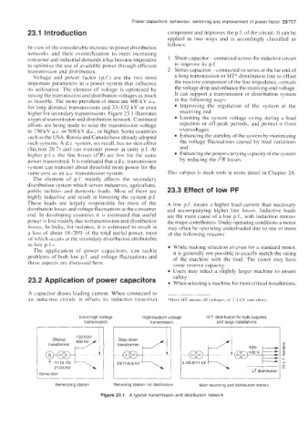
higher for secondary transmissions. Figure 23. I illustrates receiving end
a typical transmission and distribution network. Continued Limiting the system voltage swing during a load
efforts are being made to raise the transmission voltage rejection or off-peak periods, and protect it from
to 750 kV ax. or 500 kV d.c., or higher. Some countries overvoltages
such as the USA, Russia and Canada have already adopted Enhancing the stability of the system by minimizing
such systems. A d.c. system, we recall, has no skin effect the voltage fluctuations caused by load variations
(Section 28.7) and can transmit power at unity p.f. At and
higher p.f.s, the line losses (I’R) are low for the same Enhancing the power-carrying capacity of the system
power transmitted. It is estimated that a d.c. transmission by reducing the I’R losses.
system can transmit about threefold more power for the
same cost as an ax. transmission system. This subject is dealt with in more detail in Chapter 24.
The element of p.f. mainly affects the secondary
distribution system which serves industries, agriculture,
public utilities and domestic loads. Most of them are 23.3 Effect of low PF
highly inductive and result in lowering the system p.f.
These loads are largely responsible for most of the A low p.f. means a higher load current than necessary
distribution losses and voltage fluctuations at the consumer and accompanying higher line losses. Inductive loads
end. In developing countries it is estimated that useful are the main cause of a low p.f., with induction motors
power is lost mainly due to transmission and distribution the major contributors. Under operating conditions a motor
losses. In India, for instance, it is estimated to result in may often be operating underloaded due to one or more
a loss of about 18-20% of the total useful power, most of the following reasons:
of which occurs at the secondary distribution attributable
to low p.f.s. While making selection of even for a standard motor,
The application of power capacitors, can tackle it is generally not possible to exactly match the rating
problems of both low p.f. and voltage fluctuations and of the machine with the load. The motor may have
these aspects are discussed here. some reserve capacity.
Users may select a slightly larger machine to ensure
23.2 Application of power capacitors safety.
When selecting a machine for more critical installations,
A capacitor draws leading current. When connected to
an inductive circuit. it offsets its inductive (reactive) *Here HT meanr all voltages of 2.4 kV and above
Extra high voltage High1medium voltage H T distribution for bulk supplies
transmission transmission and large installations
132/220/
11115 751
2 1/24 kV
LT distribution
Generating station Receiving station 1 st distribution Main receiving and distribution station
Figure 23.1 A typical transmission and distribution network