
Page 775 - Industrial Power Engineering and Applications Handbook
P. 775
231732 Industrial Power Engineering and Applications Handbook
capacitor is fully charged, the system will experience and can be reclosed either manually or through a
an overvoltage and the arc between the moving contacts power factor correction relay to allow a pause before
of an interrupting device (a breaker or a contactor) reclosing.
may restrike even more severely than an inductive
circuit, due to higher restriking voltages (TRVs). 23.5.2 Harmonic effects and inductive
4 Some resistance andor inductance is recommended interferences
to be introduced into the switching circuit to dampen
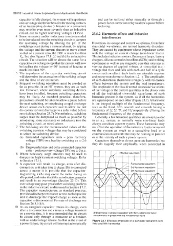
the restriking voltage by altering the p.f. of the Distortions in voltage and current waveforms, from their
switching circuit during a make or a break, by helping sinusoidal waveforms, are termed harmonic disorders.
the voltage and the current phasors to move closer They are caused by equipment whose impedance varies
so that on a current zero, the TRV is much less than with the voltage or current change (non-linear loads).
V,. See also Figures 17.1 l(a) and (b) for an inductive This includes induction motors, fluorescent lamps, battery
circuit. The situation will be almost the same for a chargers, silicon-controlled rectifiers (SCRs) and welding
capacitive switching except that the current will now equipment as well as any magnetic core that saturates at
be leading the voltage by 90" instead of lagging at varying degrees of applied voltage. A sinusoidal (a.c.)
much less than 90". voltage that rises and falls with each one half of a cycle
5 The impedance of the capacitor switching circuit causes such an effect. Such loads are saturable reactors
will determine the attenuation of the striking voltage and power transformers (Section 1.2.1). The amplitudes
and the time of arc extinction. of such distortions (harmonics) magnify with resonance
6 Frequent switching operations must be avoided as effects between the system and the load impedances.
far as possible. In an HT system, they are as such The amplitude of the thus distorted sinusoidal waveform
low. However, where automatic switching devices of the voltage or the current quantities is the phasor sum
have been installed, frequent switching operations of all the individual sinusoidal waveforms of each
may be likely. As standard practice, therefore, harmonic present in the system, as if all the harmonics
precautions should be taken to allow a pause before are superimposed on each other (Figure 23.7). A harmonic
the next switching, or introducing a rapid discharge is the integral multiple of the fundamental frequency,
device across each capacitor unit to allow the last such as the third, fifth, seventh and eleventh having a
disconnected unit discharge to a safer value before frequency of 3f, 5J 75 and I Ifrespectively ('fbeing the
reswitching (Section 25.7). Nevertheless, switching fundamental frequency of the system).
surges must be dampened as much as possible by Generally, a few harmonic quantities are always present
introducing some resistance or inductance into the in an a.c. system. as normally some non-linear loads
switching circuit, as noted above. always constitute a power system. These harmonics may
7 The following are the recommended values of the not affect the operation of the inductive loads connected
switching transient voltages that may be considered on the system as much as a capacitive load or a
to select the switching device: communication network that may be running in parallel
(a) Grounded capacitors units - peak recovery or in the vicinity of such a power system.
voltage (TRV) on a healthy switching up to 2.6 Capacitors themselves do not generate harmonics but
p,u. they do magnify their amplitudes, when connected in
(b) Ungrounded star- and delta-connected capacitor
units -peak recovery voltage (TRV) up to 3 p.u.
8 Where necessary, surge arresters may be used to
dampen the high transient switching voltages. Refer
to Section 17.1 1.
9 A capacitor will retain its charge, even after dis-
connection, as it takes time to decay. If it is connected
across a motor it is possible that the capacitor-
magnetizing kVAr may excite the motor during an
idle period, and make it act like an induction generator
and result in an overvoltage (Section 23.13). This
overvoltage may pose yet another switching problem
in the inductive circuit, as discussed in Section 17.7.
The capacitor manufacturers, as standard practice,
provide a discharge resistance across each capacitor
unit to discharge the trapped charge as soon as the
capacitor is disconnected. For rate of discharge see
Section 26.3.1(15).
10 As an energized capacitor retains its charge, even
after a disconnection and causes a voltage transient
on a reswitching, it is recommended that its circuit 3rd harmonic in phase opposition with the fundamental wave
be closed only through a contactor or a breaker, 5th harmonic in phase with the fundamental wave
with an undervoltage release. So that in the event of Figure 23.7 Effective amplitude of a particular waveform with
a power failure, the circuit will interrupt automatically third and fifth harmonics